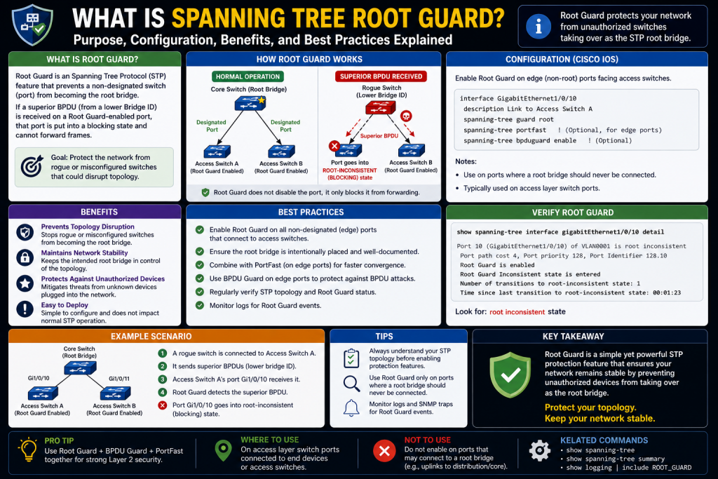
In modern enterprise networking, stability and predictability are essential for maintaining operational continuity. As organizations expand their infrastructure, adding more switches, endpoints, wireless devices, servers, and interconnected systems, network complexity grows significantly. While this growth improves scalability and connectivity, it also increases the possibility of technical failures, loops, and malicious manipulation. One of the most important technologies developed to address these concerns is Spanning Tree Protocol (STP), a foundational Layer 2 network protocol designed to prevent switching loops and broadcast storms.
Without STP, Ethernet networks containing redundant physical paths could quickly become unstable. Although redundancy is crucial for fault tolerance, multiple active paths between switches can create endless loops in which frames circulate continuously. Such loops can overwhelm network devices, saturate bandwidth, and create catastrophic outages. STP solves this by logically blocking redundant paths while preserving them for failover.
However, while STP is highly effective at loop prevention, it also introduces another challenge: root bridge selection. Since the root bridge becomes the central reference point for Layer 2 forwarding decisions, protecting its position is essential. If an unauthorized or poorly configured switch becomes the root bridge, network traffic may take inefficient paths, performance may degrade, or attackers may gain strategic influence over network traffic. Root Guard was developed to prevent such risks.
To fully understand Root Guard, it is necessary to first understand the architecture, behavior, and importance of Spanning Tree Protocol itself. This foundational knowledge reveals why Root Guard is one of the simplest yet most effective protections available to network administrators.
Why Network Loops Are Dangerous
Ethernet networks are designed to forward frames based on MAC addresses. Unlike Layer 3 routing protocols, traditional Layer 2 switching does not inherently contain mechanisms to stop frames from endlessly circulating in a looped topology.
Consider a scenario where three switches are connected in a triangle for redundancy. If one path fails, traffic can still flow through another route. This redundancy is beneficial, but if all paths remain active simultaneously, frames may duplicate and circulate infinitely.
The consequences of switching loops include:
Broadcast storms, where broadcast traffic multiplies uncontrollably
MAC address table instability, causing switches to constantly relearn device locations
Duplicate frame delivery, leading to communication confusion
Excessive CPU utilization on switches
Network-wide congestion and severe outages
Even a small loop can cripple an enterprise network in seconds. Because Ethernet frames do not include a time-to-live field like IP packets, there is no built-in expiration to stop endless circulation. STP was specifically created to address this design limitation.
The Origin and Purpose of Spanning Tree Protocol
Spanning Tree Protocol was standardized under IEEE 802.1D to provide loop-free Layer 2 topologies while preserving physical redundancy. The protocol creates a logical tree structure by selecting one switch as the root bridge and then calculating the best path from all other switches back to that root.
Rather than disabling redundancy entirely, STP selectively places certain redundant links into a blocking state. These blocked ports do not forward normal traffic unless an active path fails, at which point STP can reconverge and activate backup paths.
This approach provides:
Loop prevention
Redundancy
Automatic failover
Topology stability
Predictable forwarding paths
STP effectively allows organizations to enjoy the benefits of resilient network design without sacrificing operational reliability.
How STP Builds a Logical Topology
Spanning Tree Protocol works by electing one switch as the root bridge. The root bridge acts as the central authority for topology calculations. Every other switch determines the shortest path to this root bridge and forwards traffic accordingly.
STP topology construction involves several key steps:
Root bridge election
Root port selection on non-root switches
Designated port selection for each network segment
Blocking redundant ports
This process ensures that only one active path exists between any two network points, eliminating loops.
The resulting logical structure resembles a tree, where the root bridge serves as the trunk and downstream switches act as branches.
Understanding Bridge Protocol Data Units (BPDUs)
BPDUs are the control messages used by switches to exchange STP information. They are essential to root bridge election and ongoing topology maintenance.
BPDUs contain important information such as:
Bridge ID
Root bridge ID
Path cost
Port ID
Timers
A Bridge ID consists of:
Bridge priority
MAC address
The switch with the lowest Bridge ID becomes the root bridge. Since lower priority values are preferred, administrators can intentionally influence root bridge selection by manually lowering the priority of a chosen switch.
If priorities are equal, the switch with the lowest MAC address wins.
BPDUs are continuously exchanged so switches can detect changes, failures, or superior root claims.
The Root Bridge: Why It Matters
The root bridge is the foundation of STP operation. All path calculations are based on the root bridge’s position, making it one of the most influential devices in the network topology.
A well-chosen root bridge should be:
Highly available
High-performance
Strategically located
Reliable
Properly secured
If the wrong switch becomes root bridge, traffic paths may become inefficient. For example, a low-capacity access switch located at the network edge could suddenly become the root, forcing traffic to traverse suboptimal routes.
This can result in:
Higher latency
Reduced throughput
Congestion
Unexpected path changes
Administrative complexity
In more severe cases, a malicious actor could intentionally introduce a rogue switch advertising superior BPDUs to seize root bridge status.
How Rogue Root Bridge Attacks Work
A rogue switch can manipulate STP by advertising a lower Bridge ID than the legitimate root bridge. Since standard STP accepts superior BPDUs, nearby switches may believe the rogue switch should become the new root bridge.
This creates multiple risks:
Traffic interception
Denial of service
Topology instability
Security compromise
Network disruption
Attackers may exploit this to redirect traffic through compromised infrastructure, creating opportunities for packet inspection or traffic manipulation.
Even accidental misconfiguration can cause similar disruption. A newly installed switch with a lower priority setting could unintentionally replace the intended root bridge.
Why Standard STP Alone Is Not Enough
Although STP prevents loops, it does not inherently enforce which switch must remain root. STP’s election process is dynamic, meaning topology can change whenever a superior BPDU appears.
This flexibility is useful for adaptability but dangerous for security and predictability.
By default, STP assumes any superior BPDU is legitimate. It does not distinguish between:
Authorized infrastructure changes
Misconfigurations
Malicious devices
Temporary test equipment
Because of this, administrators need additional protective controls to preserve intentional topology design.
The Security Gap Root Guard Was Designed to Solve
Root Guard was developed specifically to enforce root bridge placement. Rather than allowing any superior BPDU to alter topology, Root Guard protects designated ports from accepting root takeover attempts.
Its primary purpose is simple:
Prevent unauthorized switches from becoming root bridge
Maintain intended network design
Preserve performance optimization
Reduce accidental topology changes
Strengthen Layer 2 security
Root Guard is particularly useful on ports where downstream switches should never be allowed to influence root bridge election.
Real-World Example of Root Bridge Protection
Imagine a corporate headquarters with a powerful core switch intentionally configured as root bridge. Multiple distribution switches connect to branch offices and access switches.
Without Root Guard:
A branch switch with lower priority could claim root
A test lab switch could accidentally disrupt production
A rogue device could alter topology
With Root Guard:
Core root status remains protected
Unauthorized superior BPDUs are rejected
Affected ports are isolated
Topology remains stable
This preserves administrative intent and minimizes disruption.
The Relationship Between STP and Organizational Security
Network security is often associated with firewalls, endpoint detection, or encryption, but Layer 2 protections are equally important. Attackers often exploit overlooked switching infrastructure because it can provide broad influence with minimal visibility.
Root Guard contributes to defense-in-depth by protecting the network’s structural control plane.
Benefits include:
Reduced attack surface
Topology consistency
Improved compliance
Fewer outages
Controlled infrastructure hierarchy
In environments where uptime is critical, such as healthcare, finance, government, or cloud operations, these protections become especially valuable.
Root Guard vs General Loop Prevention
It is important to understand that Root Guard does not replace STP. Instead, it enhances STP.
STP focuses on:
Loop prevention
Path calculation
Redundancy management
Root Guard focuses on:
Root bridge protection
Superior BPDU rejection
Topology enforcement
Think of STP as traffic engineering and Root Guard as security policy enforcement.
Together, they create a more secure and predictable switching environment.
The Strategic Importance of Controlled Topology
Network design is not random. Engineers carefully determine root bridge placement based on:
Bandwidth requirements
Redundancy models
Data center architecture
Core-distribution-access design
Latency considerations
Security segmentation
When root bridge status changes unexpectedly, these carefully planned architectures may become compromised.
Root Guard ensures that design decisions remain intact.
Common Environments Where Root Guard Is Essential
Root Guard is especially valuable in:
Enterprise campus networks
Educational institutions
Healthcare systems
Financial networks
Manufacturing plants
Large branch infrastructures
Managed service environments
In these settings, unauthorized root bridge elections can affect thousands of users.
Understanding Administrative Intent
One of the most overlooked aspects of networking is preserving administrative intent. Engineers often optimize a network for years, carefully choosing root bridges, backup paths, and failover strategies.
Without Root Guard, one accidental switch connection could undermine that work instantly.
Root Guard serves as a policy statement:
“This port should never receive a superior BPDU.”
That simple rule protects broader architectural decisions.
How Root Guard Supports Predictable Performance
Predictable traffic flow is critical for:
Voice communications
Video conferencing
Cloud applications
Storage replication
Virtualization
Industrial control systems
Unexpected topology shifts can create path inefficiencies that hurt these services.
By maintaining root bridge integrity, Root Guard contributes directly to performance stability.
The Cost of Ignoring Root Bridge Security
Organizations that ignore Root Guard may experience:
Unexpected outages
Poor failover design
Increased troubleshooting time
Security vulnerabilities
Unauthorized infrastructure influence
Reduced operational confidence
Many Layer 2 incidents stem not from hardware failure, but from preventable configuration weaknesses.
Preparing for Deeper Root Guard Implementation
Before enabling Root Guard, administrators must first understand:
Which switch should be root bridge
Which interfaces connect to downstream devices
Which ports should never accept superior BPDUs
Where flexibility is required
This strategic planning ensures Root Guard improves security without accidentally blocking legitimate infrastructure changes.
Introduction to Root Guard as a Layer 2 Security Enforcement Tool
Once network administrators understand how Spanning Tree Protocol establishes a loop-free topology, the next critical step is learning how to protect that topology from disruption. Standard STP is highly effective at preventing broadcast storms and switching loops, but by itself, it does not enforce permanent control over root bridge placement. Any switch capable of sending superior Bridge Protocol Data Units can potentially challenge the existing root bridge and alter the network’s logical design.
This creates a significant vulnerability because the root bridge serves as the central decision-maker for forwarding paths across the entire switched environment. If that position changes unexpectedly, even for a short period, network traffic patterns may shift, performance can degrade, and security risks may emerge.
Spanning Tree Root Guard addresses this issue by acting as a policy enforcement mechanism. Rather than merely participating in STP elections, Root Guard protects administrative intent by ensuring that designated interfaces do not allow unauthorized devices to influence root bridge selection.
At its core, Root Guard says:
“This port may connect to another switch, but that switch must never become root.”
This simple principle makes Root Guard one of the most powerful Layer 2 security enhancements available.
The Fundamental Purpose of Root Guard
Root Guard is designed to preserve a predetermined network hierarchy. In a properly engineered environment, administrators intentionally choose which switch should function as the root bridge based on topology, hardware capability, bandwidth, resilience, and strategic network design.
Without Root Guard, any switch advertising a superior BPDU can potentially become root bridge. This could happen because of:
Configuration mistakes
Unauthorized hardware deployment
Temporary testing equipment
Vendor default priority settings
Malicious devices
Root Guard prevents these situations by blocking root takeover attempts on protected interfaces.
Its primary goals include:
Maintaining intended root bridge placement
Preventing topology manipulation
Protecting traffic flow design
Reducing accidental outages
Improving Layer 2 security posture
How Root Guard Interacts with BPDUs
To understand Root Guard operationally, it is essential to revisit BPDUs.
Switches continuously exchange BPDUs to share topology information. Under standard STP behavior:
A switch receives a superior BPDU
The switch updates its topology understanding
A new root bridge may be elected
Traffic paths may recalculate
This dynamic adaptation is useful when legitimate infrastructure changes occur, but dangerous when unauthorized changes happen.
When Root Guard is enabled on an interface:
The port still receives BPDUs
The switch analyzes incoming BPDU quality
If the BPDU is inferior or expected, normal operation continues
If the BPDU is superior, the port is immediately moved into a root-inconsistent state
This means the superior BPDU is not accepted as a legitimate topology change.
What Is a Superior BPDU?
A superior BPDU is any BPDU advertising a better root bridge than the one currently recognized.
“Better” means:
Lower bridge priority
Lower MAC address if priorities match
Lower overall Bridge ID
For example:
Current root bridge priority = 4096
Incoming BPDU priority = 0
The incoming BPDU is superior
Without Root Guard, topology may shift.
With Root Guard, the receiving port blocks this attempt.
Understanding the Root-Inconsistent State
The root-inconsistent state is one of Root Guard’s defining behaviors.
When Root Guard detects a superior BPDU:
The port stops forwarding user traffic
The port does not shut down entirely
The interface remains operational for monitoring
STP continues evaluating BPDU conditions
This differs from administrative shutdown because Root Guard is designed to self-correct.
A root-inconsistent port behaves like a listening checkpoint. It isolates the threat while preserving the ability to automatically recover.
Key characteristics include:
No data forwarding
No topology takeover
Continuous BPDU monitoring
Automatic restoration when superior BPDUs stop
This automated protection reduces the need for constant manual intervention.
Automatic Recovery Behavior
One major advantage of Root Guard is its dynamic recovery capability.
If the rogue switch is removed, reconfigured, or stops sending superior BPDUs:
The port exits root-inconsistent state
Normal forwarding resumes
No manual reset is required
This behavior is particularly valuable in large enterprise networks where human response time may delay remediation.
For example:
An unauthorized switch is connected temporarily
Root Guard blocks the interface
The rogue device is disconnected
The interface restores automatically
This minimizes downtime while preserving security.
Where Root Guard Should Be Deployed
Root Guard should not be enabled everywhere indiscriminately. Strategic placement is essential.
Ideal deployment locations include:
Ports facing downstream access switches
Distribution-to-access layer interfaces
Enterprise edge switch uplinks
Third-party managed device connections
Campus branch interfaces
Any location where downstream devices should never control root election
Where Root Guard Should Not Be Used
Improper placement can interfere with legitimate topology flexibility.
Avoid Root Guard on:
Ports toward the intended root bridge
Core inter-switch links requiring election flexibility
Redundant paths expected to carry superior BPDUs
Dynamic infrastructure zones
Lab environments requiring root changes
Misuse can unintentionally block valid topology operations.
Root Guard in Hierarchical Network Design
Most enterprise networks use hierarchical models:
Core layer
Distribution layer
Access layer
In these designs:
Core switches are usually root bridge candidates
Distribution switches may serve as secondary root
Access switches should not become root
Root Guard is most commonly applied on ports leading from distribution switches to access switches.
This ensures:
Access layer remains subordinate
Core remains authoritative
Topology remains predictable
Example of Proper Deployment
Imagine:
Core Switch A = primary root bridge
Core Switch B = secondary root bridge
Distribution Switches = controlled intermediaries
Access Switches = endpoint connectivity
If Root Guard is enabled on distribution ports facing access switches:
Access switches cannot claim root
Rogue edge switches are blocked
Core architecture remains stable
This supports both performance and security.
Configuration Basics
Root Guard configuration is generally simple, though syntax varies by vendor.
Common workflow:
Enter privileged mode
Enter global configuration mode
Select interface
Enable Root Guard
Example structure:
configure terminal
interface [port]
spanning-tree rootguard
Some systems may use:
spanning-tree guard root
spanning-tree root-guard
spanning-tree guard
Always verify vendor-specific syntax.
Interface-Level vs Global Policy Considerations
Root Guard is typically applied per interface, not globally.
This provides precision because administrators can choose exactly which ports require root protection.
Benefits of interface-specific deployment:
Granular control
Reduced accidental disruption
Policy customization
Alignment with topology design
This targeted approach makes Root Guard adaptable across diverse infrastructures.
Vendor Variations and Implementation Nuances
Different vendors may implement Root Guard with slight differences:
Cisco commonly uses “spanning-tree guard root”
HPE/Aruba may vary
Juniper environments may use alternative Layer 2 protections
Multi-vendor infrastructures require documentation review
Despite syntax differences, the conceptual purpose remains consistent:
Protect against superior BPDU root takeover.
Monitoring Root Guard Status
Operational visibility is critical.
Common verification commands include:
show spanning-tree
show spanning-tree vlan [id]
show spanning-tree inconsistentports
Typical indicators:
ROOT_Inc
Root Inconsistent
Guard Active
Blocked by Root Guard
These outputs confirm whether a port is actively protecting topology.
Reading Root Guard Events
When analyzing logs, administrators should look for:
Superior BPDU detected
Port moved to root-inconsistent
Root Guard activated
Port restored
These logs are useful for:
Security audits
Misconfiguration analysis
Change management
Rogue device detection
Common Causes of Root Guard Activation
Root Guard activation does not always indicate an attack.
Frequent causes include:
Incorrect switch priority settings
Lab equipment connected to production
Replacement hardware defaults
Unauthorized unmanaged switches
Vendor preconfiguration
Intentional malicious insertion
Understanding context is crucial before remediation.
Root Guard vs BPDU Guard
These technologies are often confused.
Root Guard:
Prevents superior BPDU root takeover
Allows BPDU receipt
Moves to root-inconsistent state
Best for switch-to-switch boundaries
BPDU Guard:
Shuts down ports receiving any BPDU
Best for edge ports with end devices only
Protects PortFast-enabled interfaces
Root Guard controls hierarchy.
BPDU Guard prevents unexpected switch connections.
Root Guard vs BPDU Filter
BPDU Filter suppresses BPDU transmission and sometimes reception.
Risks include:
Hidden topology changes
Loop risk if misused
Reduced visibility
Root Guard is generally safer because it maintains BPDU awareness while enforcing policy.
Security Implications in Enterprise Environments
Root Guard strengthens:
Zero-trust network segmentation
Physical security assumptions
Branch office consistency
Campus architecture integrity
Third-party connection governance
It is especially useful in environments with:
Shared office spaces
Contractor access
Remote branches
Large campuses
Managed service providers
The Human Factor: Misconfiguration Prevention
Not all threats are malicious. Human error remains a leading cause of outages.
Examples:
Technician installs replacement switch
Priority left at default
New switch becomes root
Traffic paths shift
Outage occurs
Root Guard can prevent this instantly.
Performance Preservation Through Root Stability
When root bridge changes:
Convergence events occur
MAC tables update
Traffic paths recalculate
Temporary packet loss may happen
Voice and video may degrade
By preserving root consistency, Root Guard supports:
Low latency
Stable VoIP
Predictable routing
Application continuity
Integrating Root Guard into Security Policy
Mature organizations often include Root Guard in:
Standard switch templates
Branch deployment policies
Security baselines
Audit controls
Network access governance
This transforms Root Guard from optional feature into infrastructure standard.
Testing Before Production Deployment
Before enabling Root Guard widely:
Map topology
Identify legitimate root paths
Lab test configurations
Validate failover behavior
Monitor logs
Improper rollout without planning can create avoidable issues.
Documentation Best Practices
Every Root Guard deployment should document:
Protected interfaces
Intended root bridge
Secondary root bridge
Expected BPDU behavior
Exception ports
This reduces confusion during incident response.
Scaling Root Guard Across Large Networks
Large organizations often automate deployment through:
Configuration templates
Network orchestration tools
Policy engines
Infrastructure-as-code frameworks
Automation ensures consistency and reduces human error.
Operational Trade-Offs
While Root Guard is powerful, it is not universally appropriate.
Potential drawbacks:
Misplaced protections can block legitimate redundancy
Requires topology awareness
Can complicate temporary maintenance
Needs change management discipline
These are manageable through planning.
Building a Layered Defense Strategy
Root Guard works best alongside:
BPDU Guard
Port Security
802.1X
VLAN segmentation
Storm control
DHCP snooping
Dynamic ARP inspection
Together, these controls create robust Layer 2 security.
Introduction to Root Guard Beyond Initial Deployment
Implementing Spanning Tree Root Guard is an important step in protecting network topology, but enabling the feature is only the beginning. Real-world enterprise environments are dynamic. Devices are replaced, infrastructure expands, branch offices connect, contractors plug in hardware, and administrators make configuration changes under pressure. In these evolving conditions, even correctly deployed Root Guard can generate operational challenges if teams do not fully understand troubleshooting processes, monitoring techniques, and strategic long-term planning.
Root Guard is designed to preserve root bridge integrity by preventing superior Bridge Protocol Data Units from changing the intended hierarchy. While this protection is highly effective, it also introduces scenarios where legitimate business operations may be interrupted if ports enter root-inconsistent state unexpectedly. This means organizations must move beyond simple activation and develop operational maturity around Root Guard.
A mature Root Guard strategy includes:
Accurate troubleshooting
Continuous monitoring
Security alignment
Topology governance
Policy standardization
Layer 2 defense integration
When administrators understand not only how Root Guard works but also how to investigate incidents and optimize deployment, Root Guard becomes more than a protocol feature—it becomes part of an enterprise security architecture.
Why Troubleshooting Root Guard Matters
In many organizations, Layer 2 issues are among the hardest to diagnose because they can appear intermittent, localized, or misleading. A Root Guard event may initially seem like:
A failed switch port
A cable problem
VLAN misconfiguration
Traffic congestion
Hardware malfunction
In reality, Root Guard may have intentionally blocked traffic to protect the network.
Without proper visibility, teams may waste hours troubleshooting symptoms while missing the root cause. This is why understanding Root Guard-specific troubleshooting procedures is essential.
Recognizing Common Symptoms of Root Guard Activation
When Root Guard blocks a port, several symptoms may appear:
Users downstream lose connectivity
A switch uplink appears active but traffic fails
Intermittent communication disruptions occur
Network path changes unexpectedly
Monitoring systems report blocked interfaces
Redundant links appear unavailable
Because the interface itself is not necessarily administratively shut down, this can confuse less experienced administrators.
The key distinction is that Root Guard places ports into root-inconsistent state rather than disabling them completely.
Understanding the Root-Inconsistent State in Practice
A root-inconsistent port is essentially quarantined from forwarding traffic because it received superior BPDUs on an interface where such claims are prohibited.
Characteristics include:
Port remains physically up
BPDU monitoring continues
Traffic forwarding stops
Topology takeover is prevented
Automatic recovery remains possible
This behavior protects the network while allowing administrators to investigate.
Using Command-Line Verification Tools
Most enterprise switches provide commands to identify Root Guard events.
Common diagnostic commands include:
show spanning-tree
show spanning-tree vlan [vlan-id]
show spanning-tree inconsistent ports
show logging
show interfaces status
Important indicators often include:
ROOT_Inc
Root inconsistent
Guard root active
Superior BPDU received
These outputs reveal whether Root Guard is functioning correctly or whether another device is attempting unauthorized root control.
Analyzing VLAN-Specific Root Guard Behavior
Because STP often operates per VLAN in many environments, Root Guard behavior may differ across VLANs.
For example:
VLAN 10 may show normal forwarding
VLAN 20 may show ROOT_Inc
This means troubleshooting should always account for VLAN-specific topology rather than assuming a universal switch issue.
Failure to analyze VLAN granularity can lead to incomplete remediation.
Identifying the Source of Superior BPDUs
Once Root Guard activation is confirmed, the next priority is identifying which device is sending superior BPDUs.
Possible causes include:
Misconfigured production switch
Replacement hardware with lower priority
Unauthorized office switch
Testing equipment
Third-party managed hardware
Malicious rogue switch
Administrators should inspect:
Connected device MAC address
Bridge priority values
Port role
Physical location
Asset inventory
This process distinguishes between security threats and operational mistakes.
The Human Error Factor
In many Root Guard incidents, the problem is not an attacker—it is human error.
Examples include:
A technician installs a switch with default priority
A temporary lab switch is connected to production
A branch office adds unmanaged infrastructure
A vendor deploys equipment without policy review
These situations can unintentionally create superior BPDU advertisements.
Root Guard’s value is that it protects against both malice and mistakes.
Misconfiguration of Intended Root Bridge
Sometimes Root Guard alerts reveal deeper architectural problems. If a legitimate infrastructure switch repeatedly triggers Root Guard, it may indicate:
Incorrect root bridge assignment
Poor topology design
Priority inconsistency
Documentation failure
Administrative misunderstanding
In such cases, the issue is not Root Guard—it is broader design governance.
Physical Security and Rogue Device Risks
Physical access remains a major Layer 2 vulnerability. An attacker with access to an unused switchport may connect a rogue switch configured with artificially low bridge priority.
Potential goals include:
Traffic redirection
Man-in-the-middle positioning
Denial of service
Topology destabilization
Reconnaissance
Root Guard can stop this attack by rejecting superior BPDU claims before topology shifts.
However, Root Guard should complement, not replace:
Port security
802.1X
Physical access controls
Network access control policies
Recovery Procedures After Root Guard Events
When a Root Guard event occurs, recovery generally involves:
Identifying offending device
Correcting switch priority or removing rogue hardware
Confirming superior BPDUs stop
Monitoring automatic port restoration
Validating traffic flow
In most cases, no manual reset is required unless additional policies intervene.
This automatic restoration is one of Root Guard’s strongest operational advantages.
When Manual Intervention May Be Needed
Although Root Guard self-recovers, manual intervention may still be required if:
Misconfiguration persists
Rogue device remains connected
STP parameters are unstable
Administrative shutdown was added
Security policy escalation occurred
Administrators should verify root cause before restoring connectivity.
Root Guard in Change Management
Network changes frequently introduce risk.
Examples:
Office expansions
Hardware refreshes
Branch onboarding
Vendor integrations
Disaster recovery exercises
Every infrastructure change should include Root Guard review to ensure:
Protected interfaces remain accurate
New switches do not challenge root
Priority strategy remains valid
Documentation stays current
This prevents “security drift.”
Best Practices for Root Bridge Selection
Root Guard is only as effective as the root bridge strategy it protects.
Ideal root bridge characteristics:
High-performance hardware
Redundant power
Central topology placement
Stable firmware
Security hardening
Administrative oversight
Choosing a weak or unstable root bridge can create avoidable dependencies.
Primary and Secondary Root Strategy
Mature STP design often includes:
Primary root bridge
Secondary backup root bridge
Controlled failover priorities
This ensures predictable elections even during outages.
Root Guard should support this model by preventing unauthorized devices outside this hierarchy from interfering.
Layered Security with BPDU Guard
Root Guard protects switch-facing interfaces where downstream devices should not become root.
BPDU Guard protects end-user-facing interfaces where no switch should exist at all.
Combined strategy:
Access ports → BPDU Guard
Distribution-facing downstream ports → Root Guard
This layered approach significantly improves Layer 2 resilience.
Integrating Root Guard with Modern Security Frameworks
Although STP is older technology, it remains relevant in zero-trust and segmented architectures.
Root Guard supports:
Microsegmentation integrity
Branch trust boundaries
Industrial network segmentation
Healthcare infrastructure controls
Retail branch consistency
Cloud edge stability
Legacy protocol does not mean obsolete security value.
Monitoring and Alerting Best Practices
Organizations should configure alerts for:
Root-inconsistent events
Superior BPDU detection
Unexpected topology changes
Bridge priority shifts
Repeated Root Guard triggers
Proactive monitoring reduces incident response time.
Documentation as a Security Control
Strong documentation should include:
Authorized root bridges
Backup root bridges
Protected interfaces
Expected VLAN topology
Switch priority map
Exception cases
Without documentation, troubleshooting becomes reactive rather than strategic.
Training Operational Teams
Many outages worsen because frontline teams misunderstand Layer 2 protections.
Training should cover:
STP fundamentals
Root Guard purpose
Command interpretation
Recovery workflows
Security implications
This ensures Root Guard is respected rather than bypassed.
Scaling Root Guard Across Multi-Site Organizations
Large enterprises should standardize Root Guard through:
Golden configuration templates
Automation platforms
Policy engines
Compliance audits
Site deployment checklists
Consistency is critical at scale.
Balancing Security and Flexibility
Not every port should be aggressively protected. Overuse can reduce legitimate flexibility.
Key principle:
Protect where hierarchy must remain fixed, allow flexibility where design requires adaptation.
Strategic deployment is more effective than universal deployment.
Root Guard in Disaster Recovery Planning
During failover events, organizations must ensure Root Guard does not unintentionally block legitimate backup paths.
Disaster recovery testing should validate:
Backup root bridge assumptions
Priority transitions
Failover behavior
Recovery timing
Policy compatibility
This prevents resilience controls from conflicting.
Auditing Root Guard Effectiveness
Periodic audits should answer:
Are intended root bridges still optimal?
Have new ports been left unprotected?
Are policies consistent?
Have repeated incidents occurred?
Is physical security adequate?
Security controls degrade without review.
The Cost of Neglecting Root Guard
Ignoring Root Guard can lead to:
Rogue topology control
Performance instability
Longer outages
Security breaches
Operational unpredictability
In contrast, Root Guard offers low-cost, high-impact protection.
Building a Long-Term Layer 2 Governance Model
Root Guard should be part of broader governance that includes:
Switch hardening
Port authentication
Topology mapping
Configuration baselines
Periodic audits
Training
Incident response
This transforms isolated features into systemic resilience.
Future Relevance of Root Guard
Even as software-defined networking evolves, traditional Ethernet switching remains widespread in:
Campuses
Factories
Healthcare
Retail
Education
Hybrid enterprise
As long as STP-based environments exist, Root Guard remains valuable.
Strategic Mindset: From Feature to Policy
The most successful organizations stop treating Root Guard as a command and start treating it as policy.
This mindset shift means:
Intentional architecture
Controlled hierarchy
Security integration
Operational discipline
Long-term resilience
Conclusion
Spanning Tree Root Guard is far more than a basic switch feature—it is a strategic control that protects one of the most fundamental elements of Layer 2 networking: root bridge authority. While enabling Root Guard is simple, mastering it requires deeper understanding of troubleshooting, monitoring, topology governance, and organizational policy.
By learning how to recognize root-inconsistent states, analyze superior BPDUs, investigate misconfigurations, and align Root Guard with broader security practices, administrators transform Root Guard from a passive setting into an active component of enterprise defense.
Its value lies not only in blocking rogue switches, but also in preserving network design, reducing human error, strengthening operational predictability, and supporting scalable governance.
In an era where cybersecurity often focuses on advanced threats, Root Guard serves as a reminder that foundational infrastructure protections still matter. A well-protected network is not just one that blocks external attacks—it is one that preserves internal architectural integrity.
For organizations committed to uptime, performance, and security, Root Guard is not optional. It is a practical, efficient, and essential safeguard for maintaining long-term Layer 2 trust.
Continue exploring the technologies and certification concepts that matter most to you.