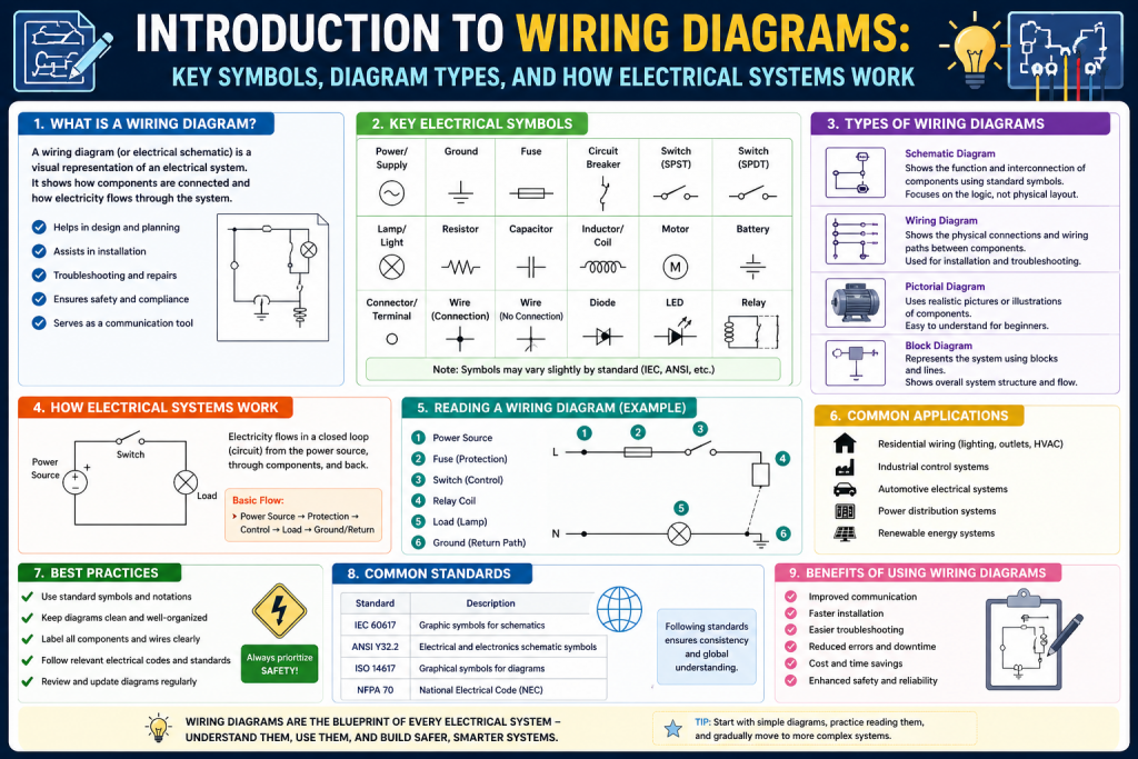
A wiring diagram is a visual representation that shows how electrical components are connected within a system. It provides a structured way to understand how electricity flows from one component to another, making it easier to design, install, and maintain electrical and networking systems. These diagrams are widely used by electricians, engineers, technicians, and even individuals working on home improvement projects.
At its core, a wiring diagram acts as a guide that removes guesswork. Instead of trying to figure out how wires are connected by physically tracing them, users can rely on a diagram that clearly illustrates every connection. This visual clarity makes it possible to understand even complex systems with relative ease.
Wiring diagrams are used in a variety of environments, from simple residential setups to advanced industrial systems. They are also an essential part of modern IT infrastructure, where they help map out connections between devices such as servers, routers, and switches. By providing a clear overview of how components interact, wiring diagrams make it easier to manage systems efficiently.
The Purpose and Importance of Wiring Diagrams
The primary purpose of a wiring diagram is to show how components are connected and how electricity flows through a system. This information is crucial for ensuring that systems function correctly and safely. Without a wiring diagram, it would be difficult to understand how different parts of a system work together.
One of the most important benefits of wiring diagrams is their ability to reduce errors. When connections are clearly defined, there is less chance of making mistakes during installation or maintenance. This is especially important in systems where incorrect wiring can lead to serious problems, such as equipment damage or safety hazards.
Wiring diagrams also improve efficiency. Instead of spending time trying to understand a system by examining physical connections, users can quickly refer to a diagram to get the information they need. This saves time and makes it easier to complete tasks accurately.
Another key advantage is communication. In projects where multiple people are involved, a wiring diagram ensures that everyone has a clear understanding of the system. This consistency helps prevent misunderstandings and ensures that work is carried out correctly.
Wiring Diagrams in Everyday Applications
Wiring diagrams are not limited to professional environments. They are commonly used in everyday situations, making them a valuable tool for anyone working with electrical or electronic systems. For example, when installing lighting fixtures, setting up home appliances, or connecting entertainment systems, wiring diagrams provide clear guidance on how to make the necessary connections.
In residential settings, wiring diagrams are often used to plan electrical layouts. They show where outlets, switches, and lighting fixtures should be placed and how they should be connected. This helps ensure that the system is both functional and safe.
In office environments, wiring diagrams play a key role in organizing network connections. They help manage the connections between computers, printers, and other devices, making it easier to maintain and troubleshoot the system. This is particularly important in businesses where reliable connectivity is essential.
Wiring diagrams are also widely used in automotive systems. Modern vehicles rely on complex electrical systems, and wiring diagrams help technicians understand how these systems are connected. This makes it easier to diagnose and repair issues.
Role of Wiring Diagrams in IT Infrastructure
In the world of information technology, wiring diagrams are essential for managing network infrastructure. They provide a clear representation of how devices are connected, helping IT professionals understand and maintain complex systems.
For example, in a local area network, a wiring diagram shows how computers, switches, routers, and servers are connected. This makes it easier to identify issues, plan upgrades, and ensure that the network operates efficiently. Without a diagram, managing a network would be much more difficult.
In larger environments such as data centers, wiring diagrams become even more important. These facilities often contain thousands of cables and devices, making it essential to have a clear map of all connections. Wiring diagrams help organize this complexity, ensuring that everything is properly connected and easy to manage.
They also play a crucial role in troubleshooting. When a problem occurs, IT professionals can refer to the wiring diagram to trace connections and identify the source of the issue. This reduces downtime and helps maintain system reliability.
Simplifying Complex Systems Through Visualization
One of the most significant advantages of wiring diagrams is their ability to simplify complex systems. Electrical and networking systems can involve a large number of components and connections, making them difficult to understand without a visual representation.
A wiring diagram breaks down this complexity into a clear and organized format. By showing each component and its connections, it allows users to see how the system is structured and how it operates. This makes it easier to understand the relationships between different parts of the system.
Visualization also helps users identify patterns and potential issues. For example, if a connection is missing or incorrectly placed, it can be quickly spotted in the diagram. This makes wiring diagrams an invaluable tool for both design and troubleshooting.
Enhancing Safety with Wiring Diagrams
Safety is a critical consideration when working with electrical systems, and wiring diagrams play an important role in ensuring safe practices. Incorrect wiring can lead to serious hazards, including short circuits, electrical shocks, and fires.
A wiring diagram helps prevent these risks by providing clear instructions on how components should be connected. It ensures that all connections are made correctly and that safety standards are followed. This is particularly important in environments where high voltages or complex systems are involved.
Wiring diagrams also make it easier to identify potential hazards. By reviewing a diagram, users can check for issues such as overloaded circuits or improper connections. This proactive approach helps reduce the likelihood of accidents.
In addition, wiring diagrams are often used as part of safety training. They help individuals understand how systems are structured and how to work with them safely. This knowledge is essential for anyone involved in electrical or networking work.
Supporting Troubleshooting and Maintenance
When a system is not functioning properly, a wiring diagram becomes an essential tool for troubleshooting. It allows users to trace connections and identify where the problem might be occurring.
Instead of checking each connection manually, users can follow the diagram to locate the issue more quickly. This saves time and makes the troubleshooting process more efficient. It also reduces the risk of causing additional problems during the process.
Maintenance is another area where wiring diagrams are extremely useful. Regular maintenance is necessary to keep systems operating smoothly, and a wiring diagram provides a clear reference for performing maintenance tasks. It helps ensure that all components are checked and maintained correctly.
By providing a detailed overview of the system, wiring diagrams make it easier to keep everything in good working condition. This helps extend the lifespan of equipment and reduces the need for costly repairs.
Guiding Installation and System Setup
Wiring diagrams are essential during the installation phase of any system. They provide a step-by-step guide on how to connect components, ensuring that everything is set up correctly from the beginning.
During installation, even a small mistake can lead to significant problems later on. A wiring diagram helps prevent these mistakes by clearly showing where each wire should go and how components should be connected. This guidance is especially important for complex systems.
For beginners, wiring diagrams provide a valuable learning tool. They offer a clear and structured way to understand how systems are assembled, making it easier to complete installations with confidence. For experienced professionals, they serve as a reliable reference that ensures accuracy.
Proper installation is critical for system performance and safety. By following a wiring diagram, users can ensure that their systems are set up correctly and ready to operate efficiently.
Assisting in System Planning and Design
Before a system is built, it must be carefully planned and designed. Wiring diagrams play a key role in this process by providing a visual representation of the proposed system.
Designers and engineers use wiring diagrams to map out connections and determine how components will interact. This allows them to evaluate different configurations and choose the most effective design. It also helps identify potential issues before installation begins.
Planning with a wiring diagram ensures that the system will be organized and efficient. It allows for better use of space and resources, reducing waste and improving overall performance. This is particularly important in large-scale projects where careful planning is essential.
In addition, wiring diagrams provide documentation that can be used for future reference. This makes it easier to maintain and upgrade the system over time.
Improving Communication and Collaboration
In projects involving multiple people, clear communication is essential. Wiring diagrams provide a common reference that everyone can use to understand the system. This helps ensure that all team members are working with the same information.
By using standardized symbols and layouts, wiring diagrams make it easier for individuals from different backgrounds to interpret the information. This is especially important in large projects where teams may include electricians, engineers, and IT professionals.
Collaboration becomes more efficient when everyone has access to a clear and accurate diagram. It reduces the likelihood of misunderstandings and ensures that work is completed correctly. This leads to better outcomes and more successful projects.
Key Elements That Make Wiring Diagrams Effective
Wiring diagrams are made up of several key elements that work together to convey information clearly. Understanding these elements is essential for reading and creating diagrams.
Symbols are used to represent different components, such as switches, resistors, and motors. These symbols provide a standardized way to identify parts, making diagrams easier to read.
Lines represent the connections between components. They show how electricity flows through the system and how different parts are linked. The layout organizes these elements in a logical way, making the diagram easy to follow.
Labels provide additional information about components and connections. They help users understand the function of each part and ensure that the correct components are used.
Together, these elements create a complete picture of the system, allowing users to understand how it works and how to interact with it.
Introduction to the Core Structure of Wiring Diagrams
After understanding the basic concept and importance of wiring diagrams, the next step is to explore how these diagrams are structured. A wiring diagram is not just a random collection of symbols and lines. It is a carefully organized visual system that follows specific rules and standards. These rules ensure that anyone reading the diagram can interpret it correctly without confusion.
The structure of a wiring diagram is what makes it effective. Without proper organization, even a simple system could become difficult to understand. Each element in the diagram has a purpose, and together they create a complete picture of how a system operates. By learning about these elements, you can improve your ability to read, create, and analyze wiring diagrams.
Understanding Symbols and Their Meaning
Symbols are one of the most important parts of a wiring diagram. They represent the various components within a system, such as switches, resistors, motors, lights, and connectors. Instead of drawing realistic images of these components, diagrams use simplified symbols that are easy to recognize.
These symbols are standardized, which means they follow widely accepted conventions. This standardization allows professionals from different backgrounds to understand the same diagram without needing additional explanation. For example, a switch symbol will look the same in most diagrams, regardless of where it is used.
Learning these symbols is essential for anyone working with wiring diagrams. Once you become familiar with them, you can quickly identify components and understand their roles within the system. This knowledge also helps you avoid mistakes, as you can easily distinguish between different types of components.
Symbols are often accompanied by labels that provide additional information. These labels might include the name of the component, its rating, or its function. Together, symbols and labels create a clear and informative representation of the system.
The Role of Lines and Connections
Lines in a wiring diagram represent the connections between components. They show how electricity flows from one part of the system to another. Without these lines, it would be impossible to understand how components are linked.
Different types of lines can be used to convey different meanings. Solid lines typically represent direct electrical connections. These are the main pathways through which electricity flows. Dashed or dotted lines may indicate alternative connections, control signals, or non-electrical relationships.
The way lines are drawn is also important. In a well-designed diagram, lines are arranged in a way that minimizes confusion. They are usually straight and avoid unnecessary crossings. When lines do cross, special symbols or markings may be used to indicate whether the wires are connected or simply passing over each other.
Understanding connections is key to interpreting a wiring diagram. By following the lines, you can trace the path of electricity and see how the system operates. This skill is particularly useful when troubleshooting, as it allows you to identify where a problem might be occurring.
Importance of Labels and Annotations
Labels and annotations provide additional details that make wiring diagrams easier to understand. While symbols and lines show the structure of the system, labels explain what each part does and how it should be used.
For example, a label might indicate the voltage of a power source, the resistance of a component, or the name of a connection point. These details are essential for ensuring that the system is built and operated correctly.
Annotations can also include notes that provide instructions or warnings. These notes might explain how a component should be installed or highlight potential safety concerns. By including this information directly in the diagram, designers can ensure that users have all the information they need.
Clear labeling is especially important in complex systems. Without it, users might struggle to identify components or understand their functions. Good labeling improves clarity and reduces the risk of errors.
Layout and Organization of Wiring Diagrams
The layout of a wiring diagram plays a major role in its readability. A well-organized diagram is easy to follow and understand, while a poorly designed one can be confusing and difficult to use.
In most wiring diagrams, components are arranged in a logical order. For example, power sources might be placed on one side of the diagram, while loads are placed on the other. This arrangement makes it easier to trace the flow of electricity from start to finish.
Spacing is also important. Components should be placed far enough apart to avoid clutter, but close enough to show their relationships. Lines should be drawn in a way that keeps the diagram neat and organized.
Consistency is another key factor. Using the same style, symbols, and layout throughout the diagram helps maintain clarity. This is particularly important in large systems, where multiple diagrams may be used together.
A good layout not only makes the diagram easier to read but also improves its usefulness as a tool for planning and troubleshooting.
Types of Wiring Diagrams
Wiring diagrams can be categorized into different types based on their purpose and level of detail. Each type serves a specific function and is used in different situations. Understanding these types is essential for choosing the right diagram for a particular task.
The three main types of wiring diagrams are schematic diagrams, circuit diagrams, and network diagrams. While they all represent connections, they do so in different ways and with different levels of detail.
Schematic Diagrams
Schematic diagrams focus on the logical relationships between components rather than their physical placement. They use symbols to represent components and lines to show connections, but they do not show the actual layout of the system.
The main purpose of a schematic diagram is to explain how a system works. It provides a simplified view that highlights the flow of electricity and the interactions between components. This makes it easier to understand the overall operation of the system.
Schematic diagrams are commonly used in the design and analysis stages of a project. Engineers use them to plan systems and test ideas before moving on to more detailed diagrams. They are also useful for teaching and learning, as they provide a clear overview of how systems function.
Because they do not show physical details, schematic diagrams are not typically used for installation. Instead, they serve as a conceptual guide that helps users understand the system at a high level.
Circuit Diagrams
Circuit diagrams are more detailed than schematic diagrams. They show not only the connections between components but also additional information such as component values and sometimes their physical arrangement.
These diagrams are used to understand how a system operates in more detail. They provide the information needed to build, analyze, and troubleshoot circuits. For example, a circuit diagram might show the exact resistance of a resistor or the voltage of a power source.
Circuit diagrams are widely used in electronics and electrical engineering. They are essential for designing and testing circuits, as well as for diagnosing problems. By providing a detailed view of the system, they allow users to identify issues and make adjustments.
Unlike schematic diagrams, circuit diagrams may include some physical details, but they still focus primarily on the electrical relationships between components.
Network Diagrams
Network diagrams are used to represent connections in communication and data systems. They are particularly important in IT infrastructure, where they help map out the relationships between devices such as computers, routers, switches, and servers.
These diagrams show how data flows through a network and how devices are connected. They can be used to plan network layouts, manage connections, and troubleshoot issues. In many cases, network diagrams also include information about IP addresses, protocols, and other technical details.
Network diagrams are essential for maintaining efficient and reliable communication systems. They provide a clear overview of the network, making it easier to identify problems and implement solutions.
In large organizations, network diagrams are often used to document the entire infrastructure. This documentation is crucial for managing complex systems and ensuring that they continue to operate smoothly.
Comparing Different Types of Diagrams
Each type of wiring diagram has its own strengths and limitations. Schematic diagrams are excellent for understanding how a system works, but they do not provide enough detail for installation. Circuit diagrams offer more detail, making them suitable for building and troubleshooting systems. Network diagrams focus on data connections, making them essential for IT environments.
Choosing the right type of diagram depends on the task at hand. For example, if you are designing a new system, a schematic diagram might be the best choice. If you are building or repairing a system, a circuit diagram would be more useful. For managing a network, a network diagram is essential.
Understanding these differences allows you to use wiring diagrams more effectively. It also helps you communicate more clearly with others, as you can choose the type of diagram that best suits your needs.
The Evolution of Wiring Diagrams
Wiring diagrams have evolved significantly over time. In the past, they were drawn by hand, which made them time-consuming to create and difficult to modify. Today, most wiring diagrams are created using digital tools, which offer greater flexibility and accuracy.
Modern software allows users to create detailed diagrams بسرعة and easily. These tools often include libraries of standardized symbols, making it simple to design professional-quality diagrams. They also allow for easy editing, so changes can be made without starting from scratch.
Digital diagrams can also be shared and stored electronically, making them more accessible. This is especially important in large projects, where multiple people need to access and update diagrams.
The evolution of wiring diagrams has made them more powerful and versatile. They are now an integral part of modern engineering and IT practices.
Common Mistakes in Wiring Diagrams
Despite their usefulness, wiring diagrams can sometimes be misinterpreted or poorly designed. Common mistakes include using incorrect symbols, failing to label components, and creating cluttered layouts.
These mistakes can make diagrams difficult to understand and increase the risk of errors. To avoid these issues, it is important to follow best practices and use standardized symbols and clear labeling.
Another common mistake is ignoring the importance of layout. A poorly organized diagram can be just as confusing as no diagram at all. Taking the time to create a clean and logical layout can greatly improve the effectiveness of a wiring diagram.
By being aware of these common mistakes, you can create better diagrams and use them more effectively.
Introduction to Practical Use of Wiring Diagrams
After exploring the fundamentals, components, and types of wiring diagrams, it is important to understand how they are applied in real-world situations. Wiring diagrams are not just theoretical tools; they are actively used in industries, homes, and IT environments to design, manage, and maintain systems. Their real value becomes clear when they are used to solve problems, organize complex setups, and guide installations.
This section focuses on how wiring diagrams are applied in different fields, how they are created using modern tools, and how they can be interpreted effectively. By mastering these aspects, individuals can move from basic understanding to practical expertise.
Applications in Network Infrastructure
In modern organizations, network infrastructure is the backbone of communication and data exchange. Wiring diagrams play a central role in designing and maintaining these networks. They provide a visual representation of how devices are connected, ensuring that data flows efficiently across the system.
One of the primary uses of wiring diagrams in networking is mapping local and wide-area connections. These diagrams show how different networks are linked, allowing administrators to understand the structure and identify potential bottlenecks. This is especially important in large organizations where multiple networks must work together seamlessly.
Wiring diagrams are also used to represent connections between switches, routers, and other networking devices. By clearly showing how these devices interact, they make it easier to manage traffic and ensure optimal performance. When changes are needed, such as adding new devices or upgrading equipment, the diagram provides a reliable reference.
Patch panels are another critical component in network infrastructure. Wiring diagrams help track connections within these panels, making it easier to manage cables and perform maintenance. Without a diagram, identifying specific connections in a dense panel would be extremely difficult.
Role in Data Centers
Data centers are among the most complex environments where wiring diagrams are used. These facilities house large numbers of servers, storage devices, and networking equipment, all connected through extensive cabling systems. Managing such complexity requires precise documentation, and wiring diagrams provide that clarity.
In data centers, wiring diagrams are used to map server racks and their connections. Each server must be properly connected to power sources, network switches, and storage systems. A wiring diagram ensures that these connections are organized and easy to understand.
Power distribution is another critical area. Data centers rely on power distribution units to supply electricity to equipment. Wiring diagrams show how power is distributed, helping ensure that systems operate safely and efficiently. They also make it easier to identify issues such as overloaded circuits.
Cooling systems are equally important in data centers. Wiring diagrams can be used to represent the setup of cooling equipment, ensuring that airflow and temperature control systems function correctly. This helps prevent overheating and maintains optimal performance.
Applications in Telecommunication Systems
Telecommunication systems rely heavily on wiring diagrams to manage complex connections. These systems include traditional telephone networks as well as modern internet-based communication platforms.
In voice over internet protocol systems, wiring diagrams are used to outline how devices are connected over a network. They show how signals travel between endpoints, helping technicians ensure that communication is clear and reliable.
Traditional telephone systems also benefit from wiring diagrams. These diagrams track connections between lines, switches, and endpoints, making it easier to maintain and troubleshoot the system. Even as technology evolves, many organizations continue to rely on these systems.
Fiber optic cabling is another area where wiring diagrams are essential. These cables are used for high-speed data transmission, and their connections must be carefully managed. Wiring diagrams provide a clear view of how fiber connections are arranged, helping ensure efficient communication.
Use in Residential and Commercial Settings
Wiring diagrams are widely used in both residential and commercial environments. In homes, they are essential for planning and installing electrical systems. They show how outlets, switches, and lighting fixtures are connected, ensuring that the system is safe and functional.
For example, when installing a lighting system, a wiring diagram can show how switches control lights and how power is distributed. This makes the installation process more straightforward and reduces the risk of errors.
In commercial settings, wiring diagrams are used to manage more complex systems. These might include lighting, security systems, and network connections. By providing a clear overview of the system, wiring diagrams make it easier to maintain and upgrade these systems.
They are also used in building design, where they help architects and engineers plan electrical layouts. This ensures that systems are integrated effectively and meet all necessary requirements.
Tools and Software for Creating Wiring Diagrams
Creating wiring diagrams has become much easier with the use of modern tools and software. These tools provide features that simplify the design process and improve accuracy.
Computer-aided design software is commonly used for creating detailed wiring diagrams. These programs offer a wide range of tools for drawing components, connecting them, and organizing the layout. They also include libraries of standardized symbols, making it easier to create professional diagrams.
Diagramming tools provide a more user-friendly option for simpler diagrams. They allow users to quickly create layouts without needing advanced technical skills. These tools are often used for basic electrical or network diagrams.
Online platforms have also become popular. They allow users to create diagrams directly in a web browser, making them accessible from anywhere. This is particularly useful for collaboration, as multiple users can work on the same diagram.
These tools not only make it easier to create diagrams but also improve their quality. Features such as automatic alignment and error checking help ensure that diagrams are clear and accurate.
Best Practices for Creating Wiring Diagrams
Creating an effective wiring diagram requires careful planning and attention to detail. Following best practices can help ensure that diagrams are clear, accurate, and easy to use.
One important practice is using standardized symbols. This ensures that anyone reading the diagram can understand it without confusion. Consistency in symbols and layout is also essential, as it makes the diagram easier to follow.
Accurate representation of components is another key factor. Each component should be placed correctly and connected in a way that reflects the actual system. This accuracy is critical for ensuring that the diagram can be used for installation and troubleshooting.
Clear labeling is also important. Labels should provide enough information to identify components and understand their functions. This includes naming connections, indicating values, and adding notes where necessary.
Keeping the layout organized is equally important. Components should be arranged logically, and connections should be easy to trace. Avoiding clutter and unnecessary complexity helps improve readability.
Interpreting Wiring Diagrams Effectively
Reading a wiring diagram is a skill that improves with practice. By following a structured approach, users can interpret diagrams more easily and accurately.
The first step is to identify the components. This involves recognizing the symbols and understanding what each component represents. Once the components are identified, the next step is to examine the connections.
Tracing the flow of electricity is essential for understanding how the system operates. By following the lines, users can see how power moves through the system and how components interact. This helps build a complete picture of the system’s functionality.
It is also important to pay attention to labels and annotations. These provide additional information that can clarify how the system works. Ignoring these details can lead to misunderstandings.
Practicing with different types of diagrams can help improve interpretation skills. Over time, users become more familiar with symbols and layouts, making it easier to read diagrams quickly.
Troubleshooting Using Wiring Diagrams
One of the most valuable uses of wiring diagrams is troubleshooting. When a system is not working properly, a wiring diagram provides a roadmap for identifying the problem.
The process typically begins by identifying the affected part of the system. Once this is done, the diagram can be used to trace connections and locate potential issues. This might involve checking for broken connections, incorrect wiring, or faulty components.
By following the diagram step by step, users can narrow down the source of the problem. This methodical approach reduces guesswork and increases the chances of finding the issue quickly.
Troubleshooting with a wiring diagram also helps prevent further damage. By understanding how the system is connected, users can avoid making changes that might worsen the problem.
Adapting Wiring Diagrams for System Upgrades
As systems evolve, upgrades become necessary. Wiring diagrams play a crucial role in this process by providing a clear view of the existing setup.
Before making changes, it is important to understand how the system is currently connected. A wiring diagram provides this information, allowing users to plan upgrades effectively. This helps ensure that new components are integrated smoothly.
During the upgrade process, the diagram can be updated to reflect changes. This keeps the documentation accurate and ensures that it remains useful for future reference.
In IT environments, where systems are frequently updated, maintaining accurate wiring diagrams is essential. It helps ensure that upgrades are carried out efficiently and without disruption.
Future Trends in Wiring Diagrams
As technology continues to evolve, wiring diagrams are also changing. Digital tools are becoming more advanced, offering features such as real-time collaboration and integration with other systems.
Automation is another emerging trend. Some tools can generate wiring diagrams automatically based on system configurations. This reduces the time required to create diagrams and improves accuracy.
Integration with smart systems is also becoming more common. Wiring diagrams can now be linked to monitoring systems, providing real-time information about system performance. This enhances their usefulness and makes them an even more powerful tool.
These advancements are making wiring diagrams more dynamic and accessible. They are no longer static documents but interactive tools that support modern technology.
Conclusion
Wiring diagrams are essential tools that bridge the gap between theory and practical application. They are widely used across industries, from residential installations to complex data centers and telecommunication systems. Their ability to provide a clear and organized view of connections makes them invaluable for designing, managing, and troubleshooting systems.
By using modern tools and following best practices, individuals can create accurate and effective wiring diagrams. Learning how to interpret these diagrams allows users to understand systems more deeply and solve problems with confidence.
As technology continues to advance, wiring diagrams will remain a fundamental part of electrical and networking work. Their role may evolve, but their importance will continue to grow as systems become more complex and interconnected.
Continue exploring the technologies and certification concepts that matter most to you.