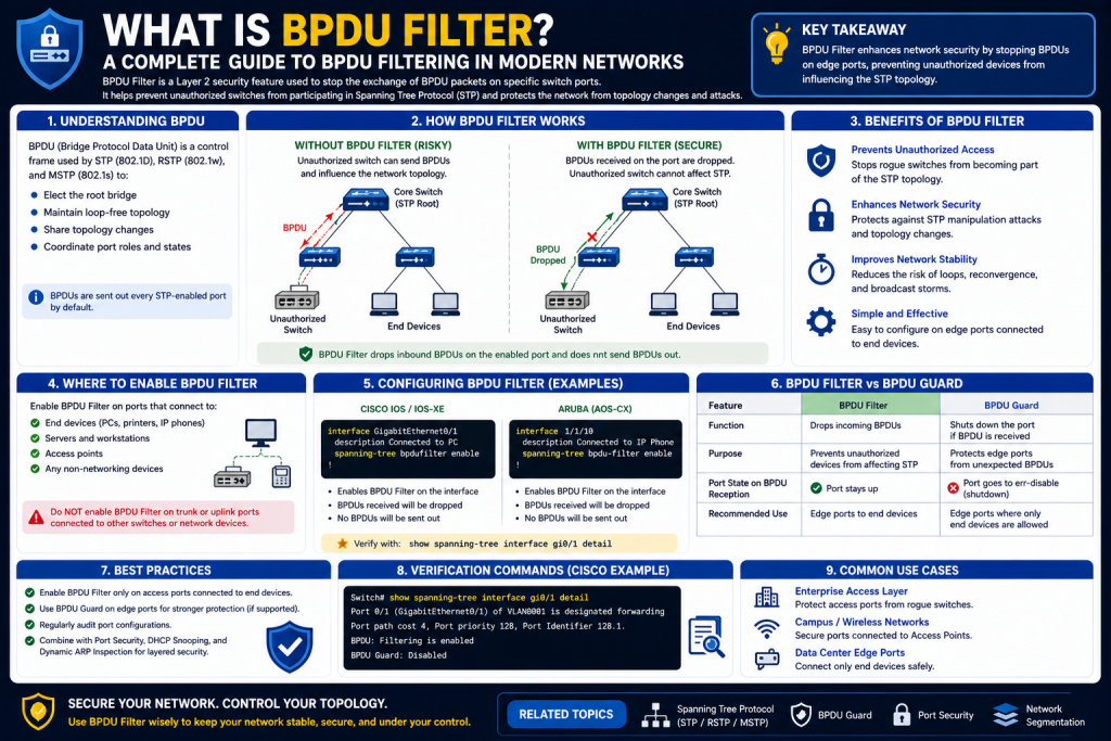
Modern business networks are designed around two critical goals: reliability and performance. To achieve reliability, network architects build redundancy into switching infrastructures so that if one connection fails, another path can immediately maintain connectivity. This redundancy is essential for uptime, but it introduces one of the biggest dangers in Layer 2 networking: switching loops. Without proper control, redundant paths can create endless frame circulation, broadcast storms, and widespread outages. Because of this, protocols and protective features that manage traffic flow are foundational to network engineering. BPDU Filter is one of those features, but understanding it properly requires first understanding the broader environment in which it operates.
BPDU Filter is closely tied to Spanning Tree Protocol, commonly known as STP. STP is the technology responsible for preventing Layer 2 loops in switched networks, while BPDUs, or Bridge Protocol Data Units, are the control messages STP uses to communicate topology information between switches. BPDU Filter controls how those BPDUs are handled on selected interfaces, allowing administrators to suppress BPDU activity under certain conditions. While this can improve segmentation and reduce some risks, it can also create major vulnerabilities if used incorrectly.
For many networking students, BPDU Filter appears to be a simple switch command. In reality, it is a strategic feature that affects topology awareness, switch communication, and network security. To use it safely, network professionals must understand Ethernet loops, STP behavior, root bridge elections, and BPDU communication fundamentals. This first section explores those foundations in depth so BPDU Filter can be understood in context rather than as an isolated command.
The Problem BPDU Filter Exists Within: Layer 2 Switching Loops
Ethernet switching operates by forwarding frames based on MAC addresses. Switches learn which MAC addresses are reachable on which ports and then use that information to make forwarding decisions. This process works efficiently when the network topology is simple and loop-free. However, enterprise networks rarely remain simple because organizations require fault tolerance.
To ensure availability, administrators often deploy multiple switches with redundant links. For example, an access switch may connect to two distribution switches, and those distribution switches may both connect to multiple core devices. These redundant links provide backup pathways if hardware or links fail. The issue is that Ethernet has no built-in loop prevention mechanism. If multiple active Layer 2 paths exist, frames can circulate indefinitely.
Unlike routed IP packets, Ethernet frames do not contain a TTL field that expires after a certain number of hops. This means a broadcast or unknown unicast frame caught in a loop can replicate continuously. The result can be catastrophic.
A broadcast storm occurs when broadcast frames endlessly circulate and multiply, consuming bandwidth across the switching fabric. As traffic increases, switch CPUs become overloaded, legitimate traffic is delayed or dropped, and users experience severe outages.
MAC address instability is another consequence. Since switches learn source MAC addresses from incoming frames, looping traffic may cause the same MAC address to appear on multiple ports repeatedly. This leads to MAC flapping, where switches constantly update their forwarding tables and lose confidence in path accuracy.
Duplicate frame delivery also becomes a problem because devices may receive the same traffic multiple times, confusing applications and reducing operational reliability.
Because of these dangers, redundancy without loop prevention is not viable in professional networking.
Why Redundancy Cannot Simply Be Eliminated
Although loops are dangerous, eliminating redundancy is not a practical solution. A network with only one path between devices is vulnerable to outages from single points of failure. A damaged cable, failed switch, or maintenance event could disconnect entire business units.
Redundancy provides several benefits:
- Fault tolerance
- High availability
- Load distribution opportunities
- Maintenance flexibility
- Disaster resilience
The challenge is balancing redundancy with loop prevention. Networks need backup paths available without allowing simultaneous active loops. This challenge is solved through Spanning Tree Protocol.
What Spanning Tree Protocol Does
Spanning Tree Protocol is a Layer 2 control protocol that creates a loop-free logical topology while preserving physical redundancy. It does this by evaluating all available switch paths and selectively blocking certain interfaces so only one active path exists between network segments.
If an active link fails, STP can recalculate the topology and activate a previously blocked path. This allows networks to maintain resilience without risking endless frame loops.
The main goals of STP are:
- Prevent Layer 2 loops
- Maintain redundancy
- Provide failover
- Stabilize switching behavior
- Protect network performance
STP essentially turns a potentially dangerous mesh of redundant links into a controlled tree structure.
The Root Bridge: Central Control of STP
Every STP topology revolves around the root bridge. This is the switch that serves as the logical center of the spanning tree. All other switches calculate their best path relative to the root bridge.
Root bridge election is based on Bridge ID, which consists of:
- Bridge priority
- MAC address
The switch with the lowest Bridge ID becomes root.
This election process is critical because traffic patterns and path selections are shaped by root bridge placement. In well-designed networks, administrators manually configure core or distribution switches to become root bridges to ensure optimal forwarding efficiency.
If an unauthorized or poorly configured device advertises superior BPDUs and becomes root, the network topology may change unexpectedly. This could degrade performance or create security concerns. BPDU-related features help mitigate such risks.
Understanding BPDUs: The Language of Spanning Tree
Bridge Protocol Data Units are special control frames exchanged between switches to share topology information. They are the foundation of STP communication.
BPDUs include information such as:
- Root bridge identity
- Sender bridge identity
- Path cost to root
- Port roles
- Timer values
- Topology change notifications
Switches use BPDUs to compare network information, elect root bridges, calculate shortest paths, and detect topology changes.
Without BPDUs, switches would operate independently without coordinated loop prevention. In many ways, BPDUs function like negotiation messages that ensure every switch understands the broader Layer 2 design.
Superior and Inferior BPDUs
Not all BPDUs are equal. Switches evaluate incoming BPDUs to determine whether they represent better or worse topology information.
A superior BPDU contains more desirable information, such as:
- Lower root bridge ID
- Lower path cost
- Better sender values
An inferior BPDU represents worse information and is ignored.
This comparison system ensures that all switches converge on the best possible spanning tree structure over time.
Port Roles Within STP
STP assigns roles to ports based on topology calculations.
Root Port: The best path from a non-root switch to the root bridge.
Designated Port: The forwarding port for a network segment.
Blocked or Alternate Port: A backup path held in reserve to prevent loops.
These roles ensure one logical forwarding path while preserving backup links for failover.
Traditional STP Limitations
Original IEEE 802.1D STP was effective but relatively slow. When topology changes occurred, convergence could take 30 to 50 seconds. In modern enterprise environments, that delay could disrupt voice, video, and critical business applications.
To improve performance, Rapid Spanning Tree Protocol and Rapid PVST+ were developed.
Rapid PVST+ and Modern Switching
Rapid PVST+ is a Cisco enhancement that improves STP by providing:
- Faster convergence
- Per-VLAN spanning tree instances
- Better failover
- Faster port state transitions
Rapid PVST+ is commonly deployed in Cisco environments and is particularly relevant when discussing BPDU Filter because many implementations occur in these networks.
PortFast and Edge Port Efficiency
Not all switch ports connect to other switches. Many connect to end-user devices like desktops, printers, or phones.
Traditional STP requires ports to move through multiple states before forwarding traffic, which can delay endpoint connectivity. PortFast solves this by allowing designated access ports to enter forwarding mode immediately.
Benefits include:
- Faster user connectivity
- Quicker DHCP initialization
- Improved boot speed
However, PortFast assumes the connected device will not create loops. If another switch is connected, topology risks emerge. This is why BPDU protection features are often paired with PortFast.
What BPDU Filter Actually Does
BPDU Filter modifies how a switch port handles BPDU traffic. In general, it suppresses BPDU sending and, depending on configuration, may also suppress BPDU processing.
This means a BPDU-filtered port may:
- Stop sending BPDUs
- Ignore incoming BPDUs
- Avoid STP participation
This effectively isolates that interface from normal spanning tree behavior.
Why BPDU Filter Exists
BPDU Filter was created for specific operational goals, including:
- Preventing unnecessary BPDU traffic on edge ports
- Supporting controlled segmentation
- Limiting accidental STP interactions
- Reducing rogue root bridge risks in specific scenarios
It is not intended as a universal security tool or default access-layer configuration.
The Security Perspective
Because STP elections depend on BPDUs, malicious or unauthorized devices can potentially influence topology by sending superior BPDUs. This may allow them to become root bridge or alter forwarding paths.
BPDU Filter can reduce this possibility on selected interfaces by suppressing BPDU exchange.
However, because filtering may also suppress legitimate STP communication, it is often considered riskier than BPDU Guard for many access-layer deployments.
BPDU Filter vs BPDU Guard
Understanding the distinction is essential.
BPDU Filter suppresses BPDU communication.
BPDU Guard disables a port if BPDUs are detected.
Guard is generally safer because it enforces policy while preserving visibility. Filter can create blindness if misused.
Global vs Interface-Level BPDU Filter
Global BPDU Filter often works alongside PortFast, suppressing BPDU transmission unless BPDUs are received.
Interface-level BPDU Filter directly suppresses BPDU behavior regardless of what is detected.
This difference matters because interface-level filtering can fully disable STP protections on a port.
The Risks of Improper Use
Misconfigured BPDU Filter can:
- Allow undetected loops
- Blind STP processes
- Cause broadcast storms
- Create MAC instability
- Isolate network segments improperly
For example, connecting two switches through BPDU-filtered interfaces can create a dangerous loop because neither switch may process the BPDUs needed for topology control.
Planning Before Deployment
BPDU Filter should only be implemented after evaluating:
- Device type on the port
- Loop risk
- Topology role
- Segmentation goals
- Security requirements
This is not a casual optimization feature.
Conclusion
BPDU Filter exists within the broader architecture of STP and Layer 2 loop prevention. Before configuring BPDU Filter, network professionals must understand why switching loops occur, how STP prevents them, the role of root bridge elections, and the critical importance of BPDUs.
At its core, BPDU Filter controls whether a port participates in BPDU communication. This can be valuable in carefully planned scenarios, but because BPDUs are central to loop prevention, suppressing them without strategic intent can undermine network stability.
A strong understanding of these foundational principles is essential before moving into practical configuration, deployment strategies, and advanced BPDU Filter use cases.
i want part 2 with normal text bold headings please in 2500 words dont bold inner text .
How BPDU Filter Works: Configuration, Operational Behavior, and Real-World Use Cases
Introduction to BPDU Filter Operations
After understanding Spanning Tree Protocol, Bridge Protocol Data Units, root bridge elections, and the role of loop prevention, the next step is examining BPDU Filter itself in operational detail. BPDU Filter is not merely a command that disables protocol traffic. It is a feature that can significantly alter how a switch interface interacts with spanning tree logic. Because STP relies on continuous BPDU communication to maintain topology awareness, any feature that suppresses BPDUs must be implemented with careful precision.
BPDU Filter is often misunderstood because many networking learners assume it simply “blocks malicious BPDUs” or “improves performance.” In reality, BPDU Filter changes how a port participates in spanning tree by suppressing BPDU transmission and, depending on implementation method, potentially ignoring inbound BPDUs as well. This creates both strategic opportunities and serious risks.
When properly deployed, BPDU Filter can help isolate network segments, simplify certain edge deployments, reduce unnecessary STP traffic, and support security goals in tightly controlled environments. When misapplied, it can silently disable loop protections, making the network vulnerable to topology failures that STP would normally prevent.
This section focuses on BPDU Filter behavior, deployment models, Cisco configuration methods, practical scenarios, security implications, troubleshooting concerns, and strategic implementation considerations.
Operational Concept: What BPDU Filter Actually Changes
At a functional level, BPDU Filter suppresses Bridge Protocol Data Units on selected interfaces. This suppression can affect outgoing BPDUs, incoming BPDUs, or both depending on how the feature is configured.
Normally, STP-enabled switch ports continuously send and process BPDUs to:
- Maintain root bridge awareness
- Detect topology changes
- Prevent loops
- Identify superior switches
- Recalculate forwarding paths
When BPDU Filter is enabled, this communication is altered.
The port may stop advertising its spanning tree presence, which means neighboring devices may not recognize it as an STP participant. In some cases, the port may also stop reacting to BPDUs entirely. This effectively removes that interface from standard spanning tree behavior.
The exact consequences depend heavily on configuration type.
Global BPDU Filter Configuration
Global BPDU Filter is usually tied to PortFast-enabled access ports. In this mode, ports initially suppress BPDU transmission because they are assumed to connect only to end-user devices.
If the port receives a BPDU unexpectedly, BPDU Filter is automatically disabled and the port resumes normal STP operation.
This mode provides a balance between convenience and protection because it assumes the port is an edge interface while still allowing recovery if a switch appears.
Benefits of global BPDU Filter include:
- Reduced unnecessary BPDU traffic on edge ports
- Faster endpoint deployment
- Automatic STP restoration upon BPDU detection
- Lower risk than interface-level filtering
This approach is generally safer because the switch can still recognize unexpected Layer 2 devices.
Interface-Level BPDU Filter Configuration
Interface BPDU Filter is more aggressive. When enabled directly on a specific port, BPDU suppression remains active regardless of inbound BPDU activity.
This means:
- The port does not send BPDUs
- The port may ignore incoming BPDUs
- STP may effectively be bypassed on that interface
This configuration can be dangerous because if another switch is connected, STP protections may never activate.
While useful in niche scenarios, interface-level BPDU Filter should only be used when administrators fully control the connected device and topology.
Why the Configuration Method Matters
The distinction between global and interface-level deployment is critical because many outages result from misunderstanding this difference.
Global BPDU Filter is conditional and adaptive.
Interface BPDU Filter is fixed and absolute.
For example, if a user accidentally connects a small unmanaged switch to a globally filtered PortFast port, the switch may detect BPDUs and restore STP behavior.
If the same user connects that switch to an interface-level BPDU-filtered port, STP may remain suppressed entirely, increasing loop risk.
Cisco BPDU Filter Configuration Commands
In Cisco environments, configuration often begins at the interface level.
To enable BPDU Filter directly:
interface GigabitEthernet1/0/1
spanning-tree bpdufilter enable
To disable it:
interface GigabitEthernet1/0/1
spanning-tree bpdufilter disable
To configure global behavior with PortFast:
spanning-tree portfast bpdufilter default
Verification is typically performed using:
show running-config
or
show spanning-tree interface
Administrators should always validate whether filtering is applied globally or specifically because this determines operational behavior.
BPDU Filter and PortFast Relationship
BPDU Filter is frequently associated with PortFast because both are edge-port technologies.
PortFast assumes the connected device is not another switch and immediately transitions the interface to forwarding state.
BPDU Filter can suppress BPDU traffic on such ports, reducing unnecessary STP interactions.
However, this relationship must be carefully managed. PortFast without safeguards can already introduce risk if a switch is connected unexpectedly. Adding BPDU Filter increases that risk unless global fallback behavior is used.
For this reason, many administrators prefer PortFast with BPDU Guard instead.
BPDU Guard vs BPDU Filter in Practice
Although both features relate to BPDUs, their operational philosophies differ.
BPDU Guard treats incoming BPDUs as a security violation and disables the port.
BPDU Filter suppresses BPDU communication.
BPDU Guard is generally preferred for user-facing access ports because it preserves STP awareness while actively enforcing security.
BPDU Filter is more specialized and often reserved for scenarios where BPDU suppression itself is desirable.
Common Use Cases for BPDU Filter
BPDU Filter can be useful in several scenarios when implemented intentionally.
Access Ports for Known Endpoints
Certain devices such as printers, IP cameras, or dedicated appliances may never need STP interaction.
Filtering BPDUs can reduce protocol overhead.
Service Provider Edge Deployments
Some provider handoffs may require isolation from customer STP environments.
Lab Networks
Testing environments may use BPDU Filter for controlled experimentation.
Segmentation Objectives
Specific network segments may intentionally avoid STP interaction.
Legacy Equipment Compatibility
Older devices or specialized hardware may not respond well to STP behaviors.
When BPDU Filter Should Be Avoided
BPDU Filter should generally not be used on:
- Trunk links
- Distribution uplinks
- Core interconnects
- Unknown edge ports
- User-facing ports with unpredictable behavior
- Switch-to-switch connections
Using BPDU Filter in these environments can suppress essential topology controls.
Network Segmentation Benefits
One major reason BPDU Filter exists is segmentation.
By suppressing BPDUs on designated interfaces, administrators can isolate segments from participating in broader spanning tree decisions.
This can help:
- Prevent accidental topology influence
- Separate administrative domains
- Simplify edge designs
- Reduce exposure to external STP environments
However, segmentation without planning can also isolate critical devices unintentionally.
Security Against Rogue Root Bridge Attacks
A rogue root bridge attack occurs when an unauthorized switch advertises superior BPDUs to become root bridge.
This may lead to:
- Traffic interception
- Suboptimal forwarding
- Topology manipulation
- Service instability
BPDU Filter can reduce this threat in limited scenarios by suppressing BPDU participation.
However, Root Guard and BPDU Guard are often more effective because they preserve STP visibility while enforcing policy.
The Hidden Danger: Silent Loops
One of the greatest BPDU Filter risks is silent loop creation.
Because BPDUs are suppressed, STP may not recognize dangerous physical topologies.
For example:
Switch A connects to Switch B through two BPDU-filtered ports.
Since neither side exchanges BPDUs properly, redundant paths may both forward traffic simultaneously.
This creates:
- Broadcast storms
- Duplicate frames
- MAC flapping
- Severe outages
Unlike obvious shutdown events, silent loops can be difficult to diagnose.
Troubleshooting BPDU Filter Problems
When BPDU Filter causes network issues, symptoms may include:
- Intermittent outages
- High broadcast traffic
- MAC address instability
- Unexpected topology shifts
- Slow application performance
- Switch CPU spikes
Troubleshooting should include:
- Checking interface configs
- Reviewing PortFast settings
- Examining spanning tree states
- Monitoring MAC address tables
- Validating physical topology
Because BPDU suppression reduces visibility, diagnosis may require broader network analysis.
Best Practice: Documentation Before Deployment
Before enabling BPDU Filter, administrators should document:
- Port purpose
- Device type
- VLAN role
- STP design
- Security goals
- Recovery strategy
BPDU Filter should never be deployed casually.
Testing Before Production
Lab validation is essential.
Testing should simulate:
- Unauthorized switch connections
- Redundant path creation
- Device replacement
- Failover events
- Configuration rollback
This ensures BPDU Filter behavior aligns with design expectations.
Combining BPDU Filter with Other STP Features
BPDU Filter is often considered alongside:
- BPDU Guard
- Root Guard
- Loop Guard
- PortFast
These features can complement each other, but poor combinations can create unintended consequences.
For example, filtering BPDUs while expecting Root Guard enforcement may undermine visibility.
Strategic design is essential.
Administrative Philosophy
BPDU Filter should be treated as a specialized control, not a default security policy.
A sound philosophy is:
- Use BPDU Guard for general access security
- Use Root Guard for topology enforcement
- Use Loop Guard for unidirectional risk
- Use BPDU Filter only for intentional suppression
This minimizes unnecessary exposure.
Performance Considerations
Although BPDU Filter may reduce some control-plane processing, performance gains are usually minor compared to topology and security considerations.
The true value is control, not speed.
Human Error as a Major Risk
Many BPDU Filter incidents are not caused by technology failure but by misunderstanding.
Common mistakes include:
- Applying interface filtering instead of global
- Enabling on trunk ports
- Forgetting documentation
- Misjudging endpoint type
- Ignoring future scalability
Proper education is as important as technical skill.
Introduction to BPDU Filter in Real Network Operations
Understanding Spanning Tree Protocol, root bridge elections, and Bridge Protocol Data Units provides the theoretical foundation for BPDU Filter, but real networking requires more than theory. Administrators must understand exactly how BPDU Filter behaves on switch ports, what changes it introduces into Layer 2 topology, how vendors implement it, and how those implementation choices affect operational safety.
BPDU Filter is often misunderstood because many networking learners see it as either a security feature or a performance optimization. In reality, it is neither purely defensive nor purely performance-based. BPDU Filter is a control mechanism that changes whether a switch interface participates in STP communication. Because STP depends on BPDU exchanges to prevent loops, any suppression of BPDU traffic changes how the network evaluates topology on that port.
This means BPDU Filter is powerful but potentially dangerous. In the right environment, it can support segmentation, simplify certain edge deployments, and reduce unnecessary spanning tree interaction. In the wrong environment, it can silently disable protections that prevent catastrophic Layer 2 failures.
This section explores the operational behavior of BPDU Filter, how it works in different deployment modes, configuration techniques, implementation scenarios, risks, troubleshooting, and design considerations for real-world networks.
BPDU Filter’s Core Function: Suppressing BPDU Activity
At its most basic level, BPDU Filter suppresses the transmission of Bridge Protocol Data Units on designated interfaces. Depending on how the feature is configured, it may also affect how inbound BPDUs are processed.
Under standard STP operation, switch ports exchange BPDUs continuously to:
- Elect the root bridge
- Determine path costs
- Detect topology changes
- Maintain loop prevention
- Assign forwarding roles
- Respond to failures
When BPDU Filter is enabled, that normal exchange is altered.
The interface may stop sending BPDUs, meaning neighboring devices may not recognize it as a participating switch port in STP. In more aggressive configurations, the interface may also stop processing incoming BPDUs, effectively isolating the port from spanning tree logic.
This changes the port from an active STP participant into something closer to a silent forwarding interface.
Why BPDU Suppression Can Be Useful
Suppressing BPDUs may be beneficial in highly controlled situations because not every switch port needs to influence topology.
For example:
- User access ports connected to PCs
- Dedicated printers
- IP cameras
- Embedded industrial systems
- Certain service provider handoffs
In these scenarios, administrators may want a port to forward traffic normally without participating deeply in spanning tree calculations.
This can reduce unnecessary STP interactions and help isolate certain edge conditions.
However, usefulness depends entirely on certainty about what is connected.
The Two Primary BPDU Filter Models
BPDU Filter behavior differs dramatically depending on whether it is configured globally or directly on an interface.
Global BPDU Filter
Global BPDU Filter is typically associated with PortFast-enabled interfaces.
In this mode:
- PortFast ports suppress BPDU transmission initially
- If a BPDU is received, filtering stops
- The port resumes normal STP participation
This creates a conditional model where the port assumes it is connected to an endpoint, but if evidence suggests another switch exists, STP protections reactivate.
This approach is safer because it preserves recovery mechanisms.
Interface-Level BPDU Filter
Interface-level BPDU Filter is manually enabled on a specific interface.
In this mode:
- BPDU suppression is persistent
- The interface may ignore inbound BPDUs
- STP participation may remain disabled regardless of topology changes
This is far riskier because even if another switch is connected, the port may not properly engage STP protections.
Why the Difference Matters
The distinction between global and interface-level deployment is critical.
Global BPDU Filter behaves like a cautious assumption.
Interface-level BPDU Filter behaves like an absolute command.
This means administrators who misunderstand deployment type may accidentally disable loop prevention where they expected fallback protection.
For example, a help desk technician may later connect a small unmanaged switch to a globally filtered edge port and trigger STP recovery.
The same mistake on an interface-filtered port may create an undetected loop.
Cisco Configuration Basics
In Cisco environments, BPDU Filter is commonly configured through interface commands or global spanning tree defaults.
To enable BPDU Filter on a specific interface:
interface GigabitEthernet1/0/10
spanning-tree bpdufilter enable
To disable it:
interface GigabitEthernet1/0/10
spanning-tree bpdufilter disable
To enable globally for PortFast ports:
spanning-tree portfast bpdufilter default
Verification commands include:
show running-config
show spanning-tree interface GigabitEthernet1/0/10 detail
These commands allow administrators to validate whether BPDU Filter is active and under what scope.
Operational Comparison: BPDU Filter vs BPDU Guard
A common source of confusion is the difference between BPDU Filter and BPDU Guard.
BPDU Filter suppresses BPDU communication.
BPDU Guard disables a port if BPDUs are detected.
This difference is profound.
BPDU Guard assumes BPDUs indicate an unauthorized switch and protects the network by shutting down the port.
BPDU Filter assumes BPDU communication is unnecessary and suppresses it.
For most enterprise access ports, BPDU Guard is often preferred because it preserves STP awareness while enforcing security.
BPDU Filter is more situational.
BPDU Filter and PortFast
PortFast is designed for edge devices that do not create loops.
When PortFast is enabled:
- Ports skip listening/learning delays
- Devices connect faster
- DHCP processes accelerate
BPDU Filter may be paired with PortFast to suppress unnecessary BPDUs on those same ports.
However, PortFast alone already assumes low loop risk. Adding aggressive BPDU suppression increases the consequences if that assumption becomes false.
This is why many enterprises use:
PortFast + BPDU Guard
rather than:
PortFast + Interface BPDU Filter
Use Cases for BPDU Filter
Although risky when misused, BPDU Filter has legitimate uses.
Controlled Endpoint Deployments
Devices with zero switching capability may not need BPDU interaction.
Provider Isolation
Separating STP domains between organizations.
Specialized Embedded Systems
Industrial or operational technology devices may require minimal Layer 2 interaction.
Temporary Lab Configurations
Testing STP scenarios.
Network Segmentation
Administrative control over topology influence.
When Not to Use BPDU Filter
Avoid BPDU Filter on:
- Trunk links
- Switch uplinks
- Distribution ports
- Core links
- Hypervisor bridges
- Unknown ports
- User-modifiable environments
These environments require full topology visibility.
How BPDU Filter Supports Segmentation
Segmentation is one of BPDU Filter’s most strategic purposes.
By suppressing BPDU exchange, certain ports can be isolated from broader spanning tree calculations.
This can:
- Prevent external STP interference
- Protect internal root bridge strategy
- Simplify edge boundaries
- Reduce administrative overlap
However, segmentation without oversight can also isolate important failover paths unintentionally.
Performance Considerations
Some administrators assume BPDU Filter significantly improves performance.
In reality, BPDU traffic is relatively lightweight. Performance gains are usually modest.
Benefits are more often related to:
- Topology simplicity
- Controlled communication
- Administrative design
- Security boundaries
BPDU Filter should not be deployed solely for speed.
Major Risk: Silent Failure Conditions
The greatest BPDU Filter danger is not immediate failure but hidden failure.
A port may appear healthy while STP protections are absent.
This can allow:
- Broadcast storms
- MAC flapping
- Duplicate traffic
- Intermittent outages
- Undetected loops
Because no automatic shutdown occurs, these issues may develop gradually and become difficult to diagnose.
Troubleshooting BPDU Filter Issues
Common warning signs include:
- High broadcast traffic
- MAC address instability
- CPU spikes
- Unexpected pathing
- Intermittent endpoint disruptions
- STP inconsistencies
Troubleshooting steps include:
- Check physical topology
- Review interface configuration
- Validate PortFast behavior
- Examine spanning tree roles
- Monitor MAC address movement
- Review switch logs
Documentation is critical because BPDU Filter may suppress obvious STP indicators.
Testing Before Deployment
No BPDU Filter deployment should enter production without lab testing.
Test scenarios should include:
- Unauthorized switch connection
- Cable redundancy introduction
- Device replacement
- Failover conditions
- Mispatch events
- Configuration rollback
Testing validates assumptions before business impact occurs.
Combining BPDU Filter with Other STP Features
BPDU Filter does not operate in isolation.
Related features include:
- BPDU Guard
- Root Guard
- Loop Guard
- PortFast
- UDLD
These tools each address different topology risks.
For example:
BPDU Guard protects access ports.
Root Guard protects root bridge positioning.
Loop Guard protects against unidirectional failures.
BPDU Filter suppresses communication.
Understanding how they interact is essential to avoid policy conflicts.
Administrative Best Practices
Before enabling BPDU Filter:
- Document purpose
- Confirm endpoint type
- Evaluate future port use
- Validate topology
- Test extensively
- Monitor continuously
Never assume a port’s purpose will remain unchanged forever.
The Human Factor
Many BPDU Filter problems result not from technical design but from operational drift.
Examples include:
- Port repurposing
- Poor documentation
- Unauthorized mini-switches
- Vendor changes
- Physical moves
This is why governance matters as much as configuration.
Introduction to BPDU Filter as an Enterprise Design Strategy
By the time network professionals move beyond foundational switching concepts and operational configuration, BPDU Filter becomes more than a feature—it becomes a strategic architecture decision. In smaller environments, BPDU Filter may seem like a simple command used to suppress Bridge Protocol Data Units on edge ports. In enterprise infrastructure, however, BPDU Filter affects topology awareness, Layer 2 governance, segmentation policy, switch security posture, operational continuity, and future scalability.
This is why experienced engineers do not ask only how to configure BPDU Filter. They ask broader questions:
- Should this port participate in STP?
- What happens if this port’s role changes later?
- Could BPDU suppression create hidden loops?
- Does filtering improve security or reduce visibility?
- Is BPDU Guard or Root Guard a better alternative?
- How will this affect long-term network governance?
These questions transform BPDU Filter from a technical setting into a design philosophy.
This section explores BPDU Filter from an advanced perspective, focusing on enterprise planning, security architecture, deployment governance, change management, topology design, troubleshooting frameworks, audit strategy, and long-term operational best practices.
BPDU Filter Is a Topology Decision, Not Just a Port Setting
One of the most common mistakes in networking is viewing BPDU Filter as an isolated interface feature. In reality, enabling BPDU suppression changes how a network interprets a port’s existence within the spanning tree ecosystem.
STP relies on BPDUs for:
- Root bridge elections
- Path cost calculations
- Loop prevention
- Redundancy management
- Topology convergence
- Failover awareness
Suppressing BPDUs alters topology intelligence.
This means BPDU Filter is not simply about traffic suppression—it is about deciding whether a port should participate in Layer 2 governance.
That decision should always be intentional.
Understanding Enterprise Network Layers
Most professional networks follow a hierarchical architecture:
Access Layer
Provides endpoint connectivity for users and devices
Distribution Layer
Enforces policy, aggregates access, and often handles routing boundaries
Core Layer
Provides fast backbone transport across major infrastructure zones
BPDU Filter is generally most appropriate at the access layer because access ports are more likely to connect to devices that should not influence STP.
Distribution and core layers rely heavily on STP intelligence. BPDU suppression at these levels can remove critical visibility.
Access Layer Use Cases
Appropriate access-layer scenarios may include:
- Printers
- Security cameras
- Badge readers
- Dedicated industrial devices
- Point-of-sale systems
- Known embedded systems
In these environments, administrators may decide the device should never influence spanning tree.
Even then, policy should account for future port changes.
Why Port Purpose Drift Is a Serious Risk
A major enterprise challenge is configuration drift.
A port originally assigned to a printer today may later be repurposed for:
- A desk switch
- Wireless bridge
- Temporary conference switch
- Virtualization host
- Unauthorized unmanaged switch
If BPDU Filter remains active, yesterday’s safe deployment can become tomorrow’s outage.
This is why enterprise operations require:
- Asset tracking
- Port labeling
- Configuration standards
- Periodic audits
- Change control
BPDU Filter safety is not only about initial deployment—it is about lifecycle governance.
Security Planning Beyond Basic Rogue Switch Prevention
BPDU Filter is often introduced as a protection against rogue root bridge manipulation, but advanced security planning requires broader thinking.
Threats include:
Unauthorized Access Switches
Users connecting personal switches
Root Bridge Hijacking
Malicious superior BPDUs
Shadow IT Expansion
Unapproved network extensions
Accidental Loops
Consumer devices creating topology problems
Vendor Equipment Changes
Third-party devices altering expected behavior
BPDU Filter can suppress STP participation, but suppression alone may reduce network awareness.
For many enterprises, BPDU Guard is preferable because it enforces policy visibly.
Comparing BPDU Filter to Other STP Security Features
Advanced network design requires selecting the right tool for the right purpose.
BPDU Guard
Shuts down access ports upon BPDU detection
Root Guard
Prevents downstream devices from becoming root bridge
Loop Guard
Protects against unidirectional failures
PortFast
Accelerates edge connectivity
BPDU Filter
Suppresses BPDU communication
BPDU Filter is the most suppressive option, which means it often carries the greatest visibility tradeoff.
Strategic Rule of Thumb
Use BPDU Filter when BPDU suppression itself is the objective.
Use BPDU Guard when unauthorized switching is the concern.
Use Root Guard when root bridge integrity matters.
This distinction prevents misuse.
Global BPDU Filter vs Interface-Level Governance
Global BPDU Filter is generally safer because it can restore STP behavior if BPDUs appear.
Interface-level BPDU Filter is more dangerous because it may permanently suppress STP on that port.
From a governance perspective:
Global = Controlled assumption
Interface = Hard suppression
Enterprise policy should generally restrict interface-level use to exceptional scenarios.
Segmentation and Administrative Boundaries
One legitimate advanced use case for BPDU Filter is segmentation.
For example:
- Managed service provider demarcation
- Customer handoff boundaries
- OT/IT separation
- Specialized lab networks
- Controlled administrative zones
In these cases, BPDU suppression can prevent external STP domains from influencing internal design.
However, segmentation requires complete topology understanding. Blind segmentation can isolate critical redundancy.
Operational Documentation Standards
Every BPDU Filter deployment should include:
- Port ID
- Device purpose
- Deployment date
- Configuration scope
- Justification
- Risk notes
- Audit schedule
- Rollback plan
Without documentation, BPDU Filter becomes a hidden risk.
Change Management and Human Error Prevention
Human error causes many BPDU Filter incidents.
Examples include:
- Incorrect port reassignment
- Unplanned office moves
- Third-party installer mistakes
- Temporary switch additions
- Documentation gaps
Best practices include:
- Role-based access controls
- Standardized templates
- Configuration reviews
- Automated compliance scanning
- Network access policies
Technology alone cannot prevent administrative drift.
Monitoring and Visibility
Because BPDU Filter can suppress topology communication, monitoring becomes more important.
Recommended monitoring includes:
- MAC address flapping alerts
- Broadcast storm detection
- Switch CPU spikes
- Interface utilization anomalies
- Unauthorized device detection
- Configuration compliance audits
Monitoring compensates for reduced STP visibility.
Testing Framework Before Production Deployment
Before enabling BPDU Filter in production, administrators should simulate:
- Rogue switch insertion
- Mini-switch deployment
- Cable loops
- Device replacement
- Failover conditions
- VLAN changes
- Port reassignment
Testing validates assumptions under real operational conditions.
Failure Scenario Planning
Every deployment should answer:
- What if someone plugs in a switch?
- What if the endpoint is replaced?
- What if redundancy is added later?
- What if the device firmware changes?
- What if documentation is lost?
If these questions are unanswered, deployment may be premature.
BPDU Filter in Large-Scale Campus Networks
In campus networks, consistency is critical.
If BPDU Filter policy differs unpredictably across buildings or switch stacks:
- Troubleshooting complexity increases
- Security policy weakens
- Training burden rises
- Risk grows
Large environments benefit from standardized deployment frameworks.
Automation and Policy Enforcement
Modern enterprises often use:
- Network automation
- Configuration templates
- Compliance engines
- NAC solutions
- Intent-based networking
BPDU Filter should align with automation standards to prevent configuration drift.
Balancing Security and Visibility
A recurring BPDU Filter challenge is the tradeoff between suppression and awareness.
Suppressing BPDUs may reduce certain risks, but it can also reduce detection opportunities.
This creates a core design principle:
Never suppress visibility unless suppression provides greater strategic value than awareness.
This principle helps prevent overuse.
Training and Team Readiness
Even strong technical design can fail if support teams misunderstand implementation.
Training should cover:
- Port purpose
- Global vs interface mode
- Failure symptoms
- Rollback procedures
- Audit expectations
Operational maturity matters.
Troubleshooting Enterprise BPDU Filter Incidents
When problems occur, engineers should investigate:
- Port configuration history
- MAC movement
- Broadcast volume
- STP states
- PortFast behavior
- Physical topology changes
- Security events
Because BPDU Filter may suppress obvious STP warnings, root cause analysis often requires broader context.
Long-Term Governance Principles
Sustainable BPDU Filter deployment depends on:
- Minimalism
- Documentation
- Testing
- Review
- Monitoring
- Policy consistency
Just because BPDU Filter can be enabled does not mean it should be.
Common Enterprise Mistakes
Frequent issues include:
- Blanket access-layer deployment
- Interface-level misuse
- Poor documentation
- Ignoring future repurposing
- Overestimating security value
- Underestimating topology blindness
Avoiding these mistakes often matters more than mastering commands.
Strategic Best Practice Framework
A mature BPDU Filter strategy often follows this model:
- Default to BPDU Guard on user-facing ports
- Use PortFast where appropriate
- Reserve BPDU Filter for intentional suppression scenarios
- Prefer global mode over interface mode when possible
- Audit regularly
- Document rigorously
- Test before deployment
- Review after topology changes
This framework balances flexibility with protection.
Conclusion
BPDU Filter is a specialized spanning tree feature, but in enterprise environments it represents much more than BPDU suppression. It is a design strategy that directly affects topology awareness, segmentation, security boundaries, and operational governance.
Used correctly, BPDU Filter can support carefully controlled access-layer deployments, service boundaries, and specialized segmentation goals. Used carelessly, it can suppress essential STP protections, reduce visibility, create hidden loops, and complicate troubleshooting.
The key to successful BPDU Filter deployment is intentionality. Administrators must understand not only how BPDU Filter works, but why it is being used, where it fits into broader architecture, how it compares to BPDU Guard and Root Guard, and how it will be governed over time.
In modern networking, true expertise is not about enabling features—it is about understanding consequences. BPDU Filter is a powerful example of this principle. When deployed strategically, documented carefully, and reviewed consistently, it can be an effective tool within enterprise Layer 2 design. When used without planning, it can undermine the very stability that STP was designed to protect.
Continue exploring the technologies and certification concepts that matter most to you.