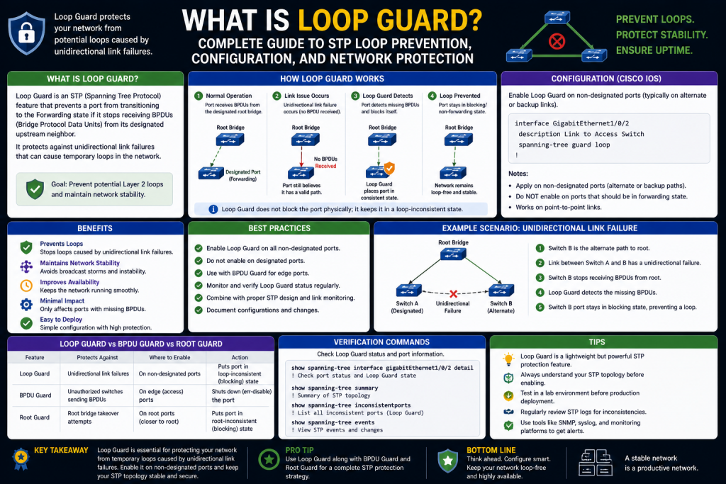
Modern enterprise networks depend heavily on redundancy. Redundant links between switches improve fault tolerance, increase availability, and provide backup paths when failures occur. However, redundancy at Layer 2 introduces one of the most dangerous threats in switching environments: network loops. A Layer 2 loop can rapidly escalate into a broadcast storm, MAC address table instability, duplicate frame transmission, and widespread outage.
Network engineers rely on Spanning Tree Protocol (STP) and its variants to prevent these loops by selectively blocking redundant paths while preserving backup links. Yet even STP itself can face vulnerabilities under certain failure conditions, particularly when Bridge Protocol Data Units (BPDUs) are unexpectedly lost. This is where Loop Guard becomes essential.
Loop Guard is a preventive enhancement to STP that protects the network from unintended forwarding state transitions caused by unidirectional link failures or BPDU loss. Rather than allowing a potentially dangerous blocked port to transition into forwarding mode, Loop Guard places it into a loop-inconsistent state until proper BPDU communication is restored.
Understanding Loop Guard requires more than memorizing a command. Engineers must understand why loops happen, how STP creates loop-free topologies, what risks still remain, and how Loop Guard strengthens those protections. This knowledge is foundational not only for production networks but also for certifications like CCNA, CCNP, and vendor-specific switching tracks.
This guide explores Loop Guard from foundational networking concepts to deployment strategy, helping you understand how it protects Layer 2 environments and why it remains relevant in modern switching infrastructures.
Understanding Network Loops
To appreciate the importance of Loop Guard, it is necessary to first understand what a network loop is and why it can be catastrophic.
A network loop occurs when there are multiple active Layer 2 paths between switches, allowing Ethernet frames to circulate endlessly. Unlike Layer 3 packets, Ethernet frames do not include a Time To Live (TTL) field that limits how long they can persist in the network. If no loop prevention mechanism exists, a frame can continue replicating indefinitely.
Consider three switches connected in a triangle topology:
Switch A connects to Switch B
Switch B connects to Switch C
Switch C connects back to Switch A
This topology provides excellent redundancy because traffic can reroute if one link fails. But without loop prevention, a broadcast frame sent from one switch can traverse all available paths repeatedly.
For example:
Switch A sends a broadcast frame
Switch B forwards it to Switch C
Switch C forwards it back to Switch A
Switch A sees it again and forwards it again
This process can continue endlessly, creating multiple severe consequences:
Broadcast Storms
Broadcast traffic multiplies exponentially, consuming available bandwidth and overwhelming network devices.
MAC Address Table Instability
Switches learn MAC addresses based on incoming ports. In a loop, the same MAC address appears on multiple interfaces rapidly, causing MAC flapping.
Duplicate Frames
Devices may receive multiple copies of the same frame, causing confusion or application errors.
High CPU Utilization
Switch processors can become overloaded processing excessive control-plane traffic.
Network Outage
Eventually, legitimate traffic is delayed or dropped, leading to widespread service disruption.
Loops are especially dangerous because they can escalate within seconds and impact entire VLAN domains.
Why Redundancy Still Matters
Despite the risks, redundant links are critical. Organizations cannot simply remove backup paths because doing so creates single points of failure. Instead, they need protocols that preserve redundancy while logically eliminating loops. STP fulfills this role.
How Spanning Tree Protocol Prevents Loops
Spanning Tree Protocol, standardized as IEEE 802.1D, was designed to maintain a loop-free Layer 2 topology while preserving physical redundancy.
STP works by identifying redundant links and selectively blocking some ports so only one active path exists between any two network segments.
The protocol accomplishes this through several steps:
Root Bridge Election
Every switch has a Bridge ID composed of:
Bridge Priority
MAC Address
The switch with the lowest Bridge ID becomes the Root Bridge, which serves as the central reference point for the spanning tree.
Path Cost Calculation
Each switch calculates the lowest-cost path to reach the Root Bridge. Lower bandwidth links have higher costs, while higher bandwidth links have lower costs.
Root Port Selection
Each non-root switch selects one Root Port, which is its best path toward the Root Bridge.
Designated Port Selection
For each network segment, one switch is selected as the Designated Bridge, and its corresponding port becomes the Designated Port.
Blocking Redundant Ports
Ports that are neither Root Ports nor Designated Ports are placed into a blocking state, preventing loops.
STP Port States
Traditional STP ports move through several states:
Blocking
Listening
Learning
Forwarding
Disabled
These transitions ensure loops are not introduced during topology changes.
Rapid PVST+ and Modern Enhancements
Rapid Per-VLAN Spanning Tree Plus (Rapid PVST+) improves convergence speed while applying STP independently per VLAN. This allows more granular traffic engineering and faster failover.
Although Rapid PVST+ improves performance, the fundamental dependency on BPDU communication remains.
The Hidden STP Vulnerability
STP assumes blocked ports continuously receive superior BPDUs from upstream switches. If these BPDUs suddenly stop arriving due to a unidirectional link issue, software bug, or certain physical failures, the blocked switch may incorrectly assume the path is no longer valid.
Without protection, that blocked port may transition to forwarding state.
If the original topology still exists elsewhere, a loop forms.
This scenario reveals that STP alone is not always enough. Additional safeguards are needed to ensure blocked ports do not mistakenly become active simply because BPDU reception fails.
What Is Loop Guard?
Loop Guard is an STP enhancement that protects non-designated ports from transitioning into forwarding mode when expected BPDUs stop arriving.
Its purpose is simple but powerful:
If a blocked or alternate port stops receiving BPDUs, Loop Guard prevents that port from becoming active automatically.
Instead, the port enters a special state called:
Loop-Inconsistent State
In this state:
The port does not forward traffic
The port does not create loops
The port remains blocked until BPDU communication resumes
Once valid BPDUs return, the port automatically recovers.
This behavior protects the network from false topology assumptions.
Why BPDU Loss Happens
BPDU loss can occur for several reasons:
Unidirectional fiber failures
Hardware interface faults
Software bugs
Misconfigured devices
Layer 1 signal issues
Faulty transceivers
In these situations, a switch may still think a link is operational at Layer 1 while control traffic is disrupted.
Loop Guard specifically addresses this gap between physical link state and STP control-plane visibility.
Loop Guard vs Standard Blocking
Without Loop Guard:
Blocked port stops receiving BPDUs
Switch assumes upstream path failed
Port may transition to forwarding
Loop may form
With Loop Guard:
Blocked port stops receiving BPDUs
Port enters loop-inconsistent state
Traffic forwarding prevented
Loop avoided
This distinction makes Loop Guard a proactive defense rather than reactive damage control.
Where Loop Guard Is Most Effective
Loop Guard is best suited for:
Switch-to-switch trunk links
Point-to-point Layer 2 connections
Redundant uplinks
Distribution-to-access links
Core-to-distribution paths
It is generally not intended for:
Access ports connected to end devices
PortFast interfaces
Edge connections
On edge ports, BPDU Guard is typically more appropriate.
Loop Guard and Unidirectional Links
One of the most important use cases for Loop Guard is unidirectional links.
A unidirectional link occurs when one side can transmit but not receive properly. For example:
Switch A sends BPDUs to Switch B
Switch B cannot send BPDUs back to Switch A
This creates asymmetric visibility that can confuse STP.
Loop Guard detects the missing BPDU condition and keeps the affected port from forwarding incorrectly.
Without Loop Guard, such failures can be devastating and difficult to troubleshoot because the physical interface may still appear “up.”
.i want part 1with bold headings in 3000 words dont bold inner text .please add title
Introduction to Loop Guard and Modern Network Protection
In enterprise networking, uptime is everything. Whether an organization supports cloud applications, VoIP communications, financial transactions, industrial systems, or internal business operations, network reliability directly impacts productivity, revenue, and security. As organizations scale, their infrastructures become increasingly redundant to prevent outages. Redundant links between switches, multiple uplinks, backup paths, and meshed topologies are all standard design choices because they improve fault tolerance. If one link fails, another can immediately take over.
However, redundancy creates a paradox in Layer 2 switching environments. The same extra paths that improve availability can also create loops—one of the most dangerous and disruptive failures in Ethernet networking.
A Layer 2 loop can rapidly overwhelm a network. Unlike routed packets at Layer 3, Ethernet frames do not inherently expire through a Time To Live mechanism. Once a loop forms, traffic can circulate endlessly, multiplying as broadcasts replicate across switching paths. This can lead to broadcast storms, MAC address instability, duplicate frames, CPU exhaustion, and widespread outages. In severe cases, a single Layer 2 loop can cripple an entire campus network in seconds.
To prevent this, network engineers rely on Spanning Tree Protocol (STP), a foundational technology that creates a loop-free logical topology while preserving physical redundancy. STP blocks certain redundant links, ensuring only one active path exists while backup links remain available if needed.
But STP is not infallible. Certain failures—particularly involving lost or unidirectional BPDU communication—can still create dangerous situations. A blocked port may incorrectly transition into forwarding mode if BPDUs are no longer received, even if the topology itself has not truly changed. This can unintentionally create a loop despite STP’s protections.
Loop Guard was developed to address this exact vulnerability.
Loop Guard is an advanced STP enhancement that protects networks from unexpected loops caused by BPDU loss on non-designated ports. Rather than allowing a blocked port to mistakenly transition to forwarding, Loop Guard places the port into a loop-inconsistent state until BPDU communication resumes. This preserves the intended topology and prevents catastrophic forwarding errors.
For network engineers, administrators, and certification candidates, understanding Loop Guard is essential. It is not just a feature—it is part of resilient network architecture.
This guide explores Loop Guard from the ground up, beginning with the nature of network loops, why they happen, how STP solves them, and where Loop Guard fits into a larger strategy of Layer 2 protection.
Understanding Layer 2 Network Loops
Before understanding Loop Guard, it is essential to understand the problem it solves.
A network loop occurs when there are multiple active Layer 2 paths between devices, allowing Ethernet frames to circulate indefinitely. In redundant switching environments, this can happen when two or more switches are interconnected in ways that permit frames to return to their origin repeatedly.
Imagine three switches:
Switch A
Switch B
Switch C
Each switch is connected to the other two, creating a triangle.
This topology is beneficial because it provides multiple paths for resilience. If one link fails, traffic can reroute. But without loop prevention, a broadcast frame sent by Switch A can reach Switch B and Switch C simultaneously, then be forwarded around the triangle endlessly.
For example:
Switch A sends a broadcast frame
Switch B forwards it to Switch C
Switch C forwards it back to Switch A
Switch A forwards it again
This process can continue indefinitely.
Why Ethernet Loops Are So Dangerous
Layer 2 loops create several critical issues:
Broadcast Storms
Broadcast frames are flooded to all devices in a VLAN. In a loop, each switch continues forwarding broadcasts repeatedly, multiplying traffic exponentially. Bandwidth becomes saturated, preventing legitimate communication.
MAC Address Table Flapping
Switches learn MAC addresses by associating source addresses with ingress ports. In a loop, the same MAC address appears on multiple interfaces repeatedly. This causes instability in the MAC table, known as MAC flapping.
Consequences include:
Incorrect forwarding decisions
Packet loss
Intermittent connectivity
Troubleshooting confusion
Duplicate Frame Delivery
Devices may receive multiple copies of the same frame. Applications not designed for duplicates may malfunction.
Control Plane Overload
Switch CPUs can become overwhelmed processing excessive broadcasts and topology changes, reducing management responsiveness.
Complete Network Failure
In severe cases, users lose connectivity entirely.
The Business Cost of Layer 2 Loops
Network loops are not merely technical inconveniences. They can disrupt:
ERP systems
Voice traffic
Wireless controllers
Authentication systems
Security appliances
Production environments
Downtime can cost organizations substantial revenue, damage reputation, and interrupt critical operations.
This is why loop prevention is foundational in network design.
Why Redundancy Cannot Be Eliminated
A simplistic solution might seem to be removing redundant links entirely. However, this would create single points of failure.
If one uplink fails:
Entire floors may lose connectivity
Data center paths may collapse
Voice services may fail
Business continuity suffers
Therefore, redundancy is mandatory—but it must be managed intelligently.
This challenge led to the creation of the Spanning Tree Protocol.
Spanning Tree Protocol: The Foundation of Loop Prevention
Spanning Tree Protocol (STP), standardized as IEEE 802.1D, was designed to solve the redundancy-versus-loop problem.
Its goal is to:
Preserve physical redundancy
Prevent logical loops
Enable automatic failover
STP creates a single logical path through the network by selectively blocking redundant interfaces.
How STP Works
STP uses Bridge Protocol Data Units (BPDUs), which are special frames exchanged between switches to determine topology.
The STP process includes several key stages.
Root Bridge Election
Every switch has a Bridge ID consisting of:
Bridge Priority
MAC Address
The switch with the lowest Bridge ID becomes the Root Bridge.
The Root Bridge serves as the logical center of the STP topology.
Path Cost Calculation
Each switch calculates the best path to the Root Bridge using path cost values based on link speed.
Higher-speed links = lower cost
Lower-speed links = higher cost
Root Port Selection
Every non-root switch selects one Root Port—the port with the lowest cost path to the Root Bridge.
Designated Port Selection
For every network segment, one switch is elected as the Designated Bridge. Its port becomes the Designated Port for that segment.
Blocking Redundant Ports
Ports that are neither Root Ports nor Designated Ports are placed into a blocking state.
This prevents loops while preserving redundancy.
STP Port States
Traditional STP ports move through several states:
Blocking
Listening
Learning
Forwarding
Disabled
Each state helps ensure safe topology convergence.
Rapid PVST+ and Faster Convergence
Modern networks often use Rapid PVST+ or Rapid Spanning Tree Protocol (RSTP), which significantly improves failover times.
Rapid PVST+ offers:
Per-VLAN spanning tree instances
Faster convergence
Improved scalability
Better traffic engineering
Despite these improvements, the protocol still depends heavily on BPDU integrity.
The Critical Role of BPDUs
BPDUs are essential because they communicate:
Root Bridge identity
Path costs
Port roles
Topology changes
If BPDU communication is disrupted, STP decisions may become inaccurate.
This is where a hidden vulnerability emerges.
BPDU Loss on Blocked Ports
STP assumes blocked ports continue receiving superior BPDUs from upstream switches.
If those BPDUs suddenly stop, the blocked switch may incorrectly assume:
The path to the root is lost
The blocked link should activate
Forwarding is safe
But if the topology still physically exists, this assumption may be false.
The blocked port could transition into forwarding mode while another forwarding path already exists.
The result:
A Layer 2 loop.
This is one of the most dangerous STP failure scenarios because the protocol itself can unintentionally permit a loop under abnormal BPDU conditions.
What Causes BPDU Loss?
BPDU loss can occur for many reasons:
Unidirectional fiber failures
Damaged cabling
Faulty optics
Software bugs
Misconfigured interfaces
Hardware failures
Signal degradation
In many cases, the physical link remains “up,” but BPDU communication fails in one direction.
This creates false topology assumptions.
Understanding Unidirectional Link Failures
A unidirectional link is one where communication works in only one direction.
For example:
Switch A sends traffic to Switch B
Switch B cannot send traffic back to Switch A
This is especially problematic because standard interface status may still show the link as operational.
STP may not immediately recognize the asymmetry.
Without additional safeguards, topology corruption can occur.
Introducing Loop Guard
Loop Guard is designed specifically to address BPDU loss on non-designated ports.
Its core purpose:
Prevent blocked ports from transitioning to forwarding when expected BPDUs disappear.
Instead of assuming the topology changed safely, Loop Guard treats BPDU silence as suspicious.
How Loop Guard Works
When Loop Guard is enabled on a switch port:
The port expects regular BPDU reception
If BPDUs stop unexpectedly
The port enters loop-inconsistent state
The port remains blocked
Traffic forwarding is prevented
Once valid BPDUs return, the port automatically recovers.
Loop-Inconsistent State Explained
Loop-inconsistent is a protective state unique to Loop Guard.
Characteristics include:
No data forwarding
No loop formation
Automatic recovery
No manual shutdown required
This state essentially freezes the port safely until BPDU integrity is restored.
Why Loop Guard Matters
Without Loop Guard:
BPDU loss may trigger forwarding
Loop may form
Broadcast storm may occur
With Loop Guard:
BPDU loss triggers protection
Port remains blocked
Loop prevented
This makes Loop Guard a critical secondary defense.
Loop Guard’s Strategic Value
Loop Guard is especially useful in:
Redundant trunk links
Distribution layer connections
Core-to-distribution uplinks
Switch-to-switch point-to-point links
Fiber uplinks vulnerable to unidirectional faults
These are the exact environments where silent BPDU failures can have large-scale consequences.
Where Loop Guard Should Not Be Used
Loop Guard is generally not intended for:
Access ports
End-user device ports
PortFast-enabled interfaces
Server edge connections without STP dependence
For these scenarios, BPDU Guard or PortFast may be more appropriate.
Loop Guard vs Physical Link State
A major advantage of Loop Guard is that it protects against logical failures, not just physical ones.
Physical link state only indicates electrical or optical connectivity.
Loop Guard validates control-plane health.
This distinction is critical because many dangerous failures occur while links appear operational.
Real-World Example
Consider two distribution switches connected redundantly.
Primary uplink = forwarding
Secondary uplink = blocked
If the blocked port stops receiving BPDUs due to a fiber issue:
Without Loop Guard:
Blocked port may forward
With Loop Guard:
Blocked port enters loop-inconsistent
This small difference can determine whether a network stays stable or collapses.
Loop Guard as a Preventive Security Measure
Though not a security tool in the traditional sense, Loop Guard supports operational security by:
Preventing accidental outages
Reducing misconfiguration impact
Protecting against silent failures
Supporting predictable topology behavior
For enterprises, this translates into resilience.
Certification Importance
Loop Guard commonly appears in:
CCNA
CCNP Enterprise
Juniper switching tracks
Data center certifications
Operational troubleshooting scenarios
Understanding not just the command, but the design logic behind it, is critical for both exams and real deployments.
Introduction to Loop Guard’s Operational Role
Understanding what Loop Guard is provides only the foundation. To deploy it effectively, engineers must understand how it functions inside a live Spanning Tree environment, how it interacts with Bridge Protocol Data Units (BPDUs), why blocked ports are vulnerable, and what specific failures Loop Guard was designed to prevent.
Loop Guard is not a replacement for STP. It is an enhancement that addresses a particular weakness in spanning tree logic: the possibility that a non-designated port could mistakenly transition from blocking to forwarding when expected BPDUs stop arriving.
This issue is subtle but critical. Many network failures are not caused by complete link loss, but by partial or unidirectional failures where physical connectivity remains but control-plane communication becomes unreliable. In these scenarios, traditional STP may interpret missing BPDUs incorrectly, potentially activating a redundant path that should remain blocked.
Loop Guard protects against this by adding a defensive checkpoint. Instead of trusting BPDU silence, it treats silence as suspicious.
To appreciate this operationally, it is essential to examine STP’s normal behavior first, then analyze how Loop Guard intervenes.
Reviewing STP Port Roles and States
Spanning Tree Protocol organizes switch ports into roles and states to maintain a loop-free topology.
Primary STP Port Roles
Root Port
Each non-root switch selects one Root Port, which is the lowest-cost path toward the Root Bridge.
Designated Port
Each network segment has one Designated Port responsible for forwarding traffic toward downstream segments.
Non-Designated Port
Ports that are redundant and unnecessary for the active topology are blocked.
These blocked ports are where Loop Guard is most relevant.
Traditional Port States
Blocking
Listening
Learning
Forwarding
Disabled
A blocked port still participates in STP by listening for BPDUs, even though it does not forward user traffic.
This detail is critical:
A blocked port is not inactive. It depends on BPDU reception to maintain awareness of topology.
Why Blocked Ports Matter So Much
Blocked ports are intentionally held in reserve as backup paths. If an active path fails, STP can transition a blocked port into forwarding to preserve connectivity.
This failover capability is essential for redundancy.
However, because blocked ports are backup paths, they can become dangerous if activated incorrectly.
A blocked port should only transition to forwarding when STP confirms a legitimate topology change.
If BPDU loss falsely signals such a change, the blocked port may activate when it should not.
This creates the precise scenario Loop Guard addresses.
BPDU Fundamentals
Bridge Protocol Data Units are STP’s control messages.
They contain:
Root Bridge information
Path cost
Sender Bridge ID
Port ID
Timers
Topology change notifications
Switches exchange BPDUs continuously to maintain spanning tree consistency.
In stable topologies:
Root Bridge sends superior BPDUs
Downstream switches relay and compare them
Blocked ports continue receiving BPDUs
STP maintains loop-free logic
BPDU continuity is therefore essential.
Normal STP Behavior During BPDU Loss
By default, STP assumes BPDU absence may indicate a topology change.
For example:
A blocked port stops receiving superior BPDUs
Switch assumes upstream path may have failed
Port may begin transitioning toward forwarding
This logic works correctly when the upstream path is genuinely gone.
But what if the link itself is only partially broken?
This is where trouble begins.
The Unidirectional Link Problem
A unidirectional link is one where traffic flows one way but not the other.
Example:
Switch A sends BPDUs to Switch B
Switch B cannot return BPDUs to Switch A
Or:
Switch B stops receiving BPDUs from Switch A due to receive-path failure
Physical link indicators may still show “up.”
This is dangerous because:
The switch believes the link exists
STP control data is incomplete
Topology assumptions become incorrect
Without Loop Guard, the blocked port may transition into forwarding.
If another forwarding path already exists, a loop forms.
Real-World Causes of BPDU Failure
BPDU communication can fail due to:
Fiber strand damage
Dirty optical connectors
Transceiver mismatch
Software defects
Interface driver issues
Miswired cabling
Patch panel faults
Layer 1 asymmetry
Hardware degradation
These issues may not fully disable the interface, making them difficult to detect through standard link-state monitoring.
Loop Guard’s Core Logic
Loop Guard modifies STP behavior on non-designated ports.
When enabled:
The port expects continuous BPDU reception
If expected BPDUs disappear
The port does not assume safe failover
The port enters loop-inconsistent state
This prevents the port from transitioning to forwarding based on uncertain information.
Loop-Inconsistent State in Detail
Loop-inconsistent is a special protective state.
Key characteristics:
Port remains logically blocked
No user traffic forwarding
No MAC learning
No loop creation
Automatic recovery when BPDUs return
Unlike err-disable conditions, loop-inconsistent does not require manual shutdown/no shutdown intervention.
This makes Loop Guard operationally efficient.
Operational Sequence Without Loop Guard
Consider two switches connected by redundant links:
Primary link = forwarding
Secondary link = blocking
If the secondary blocked port stops receiving BPDUs:
STP may assume path failure
Secondary link may transition to forwarding
Primary still forwards
Loop created
Consequences:
Broadcast storms
MAC flapping
CPU spikes
Outage
Operational Sequence With Loop Guard
Same topology:
Secondary blocked port loses BPDUs
Loop Guard detects anomaly
Port enters loop-inconsistent
Port remains blocked
Primary path continues normally
No loop
This is why Loop Guard is preventive rather than reactive.
Loop Guard Recovery Process
Recovery is automatic.
When superior BPDUs are received again:
Port exits loop-inconsistent
Returns to normal STP role
Resumes proper topology behavior
This automation minimizes downtime while preserving safety.
Why Loop Guard Focuses on Non-Designated Ports
Loop Guard primarily protects:
Root Ports
Alternate Ports
Blocking Ports
It is not designed for Designated Ports because Designated Ports originate BPDUs rather than depend on them.
Applying Loop Guard to the wrong interfaces may reduce usefulness.
Best Interface Types for Loop Guard
Ideal:
Switch-to-switch trunk links
Redundant uplinks
Distribution connections
Core links
Point-to-point Ethernet trunks
Less appropriate:
Access ports
User-facing edge ports
Server NIC edge links
PortFast interfaces
Loop Guard vs Root Guard
Though similar in name, these serve different purposes.
Loop Guard
Protects against missing BPDUs on non-designated ports.
Root Guard
Prevents unauthorized switches from becoming Root Bridge.
Root Guard enforces topology hierarchy.
Loop Guard protects blocked port state.
Together, they strengthen STP.
Loop Guard vs BPDU Guard
BPDU Guard
Disables PortFast access ports if unexpected BPDUs are received.
Loop Guard
Protects blocked switch ports when expected BPDUs disappear.
BPDU Guard protects the edge.
Loop Guard protects the infrastructure core.
Loop Guard vs UDLD
Unidirectional Link Detection (UDLD) specifically detects one-way link failures.
UDLD
Identifies physical unidirectional conditions.
Loop Guard
Protects STP topology logic when BPDUs disappear.
These features are complementary, not interchangeable.
Many best-practice environments use both.
Example Failure Scenario
A fiber pair between distribution switches:
Transmit strand operational
Receive strand damaged
Result:
Physical link up
One-way BPDU flow disrupted
Without UDLD:
Issue may persist undetected
Without Loop Guard:
Blocked port may forward
With Loop Guard:
Port protected
With UDLD:
Link shut down entirely
This layered design dramatically improves reliability.
Topology Change Considerations
Loop Guard does not interfere with legitimate topology changes.
If a true path failure occurs and proper STP recalculation happens:
Topology converges
Backup path activates correctly
Loop Guard only intervenes when BPDU silence creates ambiguity.
Vendor Support and Implementation
Cisco commonly supports:
Global Loop Guard
Per-interface Loop Guard
Juniper and other vendors may implement similar protections under different terminology.
Engineers should always verify platform-specific syntax and defaults.
Monitoring Loop Guard Events
Operational teams should monitor:
Loop-inconsistent ports
STP logs
Syslog alerts
SNMP traps
Topology changes
These indicators can reveal silent infrastructure problems before users notice major outages.
Troubleshooting Loop-Inconsistent Ports
If a port enters loop-inconsistent:
Verify fiber integrity
Check transceivers
Inspect BPDU path
Review STP role
Confirm trunk configuration
Validate VLAN consistency
Check for unidirectional faults
The goal is not merely to restore the port, but to identify why BPDUs stopped.
Misconfiguration Risks
Common mistakes include:
Enabling Loop Guard on inappropriate access ports
Ignoring repeated loop-inconsistent events
Assuming Loop Guard replaces UDLD
Poor STP root design
Incomplete documentation
Loop Guard is powerful, but only when integrated into broader Layer 2 strategy.
Loop Guard in Enterprise Architecture
Loop Guard is especially valuable in:
Campus distribution layers
Data center Layer 2 domains
Multi-switch VLAN trunks
Redundant aggregation environments
Legacy STP infrastructures
As architectures evolve toward Layer 3 segmentation, EVPN, or spine-leaf designs, Layer 2 loop risks may reduce—but traditional Ethernet switching remains widespread.
Certification and Career Relevance
Engineers pursuing:
CCNA
CCNP Enterprise
Network+ advanced switching
Juniper enterprise tracks
Should understand:
Loop Guard purpose
BPDU dependency
Loop-inconsistent state
Deployment locations
Comparison with Root Guard and BPDU Guard
These are frequent exam and interview topics.
Loop Guard as Defensive Engineering
A mature network does not rely on a single protocol for safety.
Instead, it layers:
STP
Rapid PVST+
Root Guard
BPDU Guard
Loop Guard
UDLD
This defense-in-depth approach ensures redundancy without instability.
Key Takeaway
Introduction to Practical Loop Guard Deployment
Understanding what Loop Guard is and how it functions operationally is only part of mastering it. Real value comes from knowing how to deploy it correctly, where to apply it, how it interacts with other Spanning Tree Protocol protections, how to troubleshoot it in production environments, and how to integrate it into a broader Layer 2 design philosophy.
Many network outages are not caused by a lack of technology but by incomplete implementation. A switch may support Loop Guard, but if it is applied inconsistently, misunderstood, or omitted from critical links, the network remains vulnerable. Likewise, enabling Loop Guard without understanding its relationship to Root Guard, BPDU Guard, UDLD, Rapid PVST+, and topology design can create false confidence.
This section focuses on practical engineering. It examines Cisco-style configuration methods, deployment strategy, operational best practices, monitoring, troubleshooting, and architectural planning. The goal is not simply to enable Loop Guard, but to use it intelligently as part of a resilient switching ecosystem.
Global vs Interface-Level Loop Guard Configuration
Loop Guard can typically be configured globally or per interface, depending on platform and operational goals.
Global Configuration
Global Loop Guard applies protection broadly across eligible non-designated ports in the STP domain.
This approach is often preferred because:
It standardizes deployment
It reduces human error
It ensures new interfaces inherit protection
It simplifies enterprise policy
A common Cisco command is:
spanning-tree loopguard default
This command enables Loop Guard by default on all point-to-point links where applicable.
Advantages of Global Deployment
Consistency across switching layers
Reduced configuration omissions
Faster deployment in large environments
Improved compliance with design standards
Potential Drawbacks
May affect interfaces unintentionally if topology planning is weak
Requires awareness of where STP roles exist
Needs validation during infrastructure changes
Per-Interface Configuration
Loop Guard can also be enabled on specific interfaces.
This is useful when:
Only selected uplinks need protection
Legacy environments require gradual rollout
Engineers need granular control
Specific trunks are considered high-risk
Typical configuration:
interface GigabitEthernet1/0/1
spanning-tree guard loop
Advantages of Interface-Level Deployment
Precision
Controlled testing
Customized protection
Useful for migrations
Drawbacks
Higher administrative overhead
Greater chance of inconsistency
Documentation burden
Choosing the Right Deployment Model
For most enterprises:
Global configuration is ideal for standardized infrastructure.
For specialized environments:
Selective deployment may better align with operational requirements.
The key is intentionality.
Where Loop Guard Should Be Enabled
Loop Guard works best on links where blocked ports are expected and BPDU continuity matters.
Recommended Deployment Zones
Distribution-to-Access Trunks
These often contain redundant paths and are common loop points.
Core-to-Distribution Links
Critical for enterprise backbone redundancy.
Switch-to-Switch Fiber Uplinks
Particularly vulnerable to unidirectional optical failures.
Data Center Aggregation Paths
Where redundant Layer 2 trunks still exist.
MST, PVST+, or RSTP Redundant Topologies
Any environment using STP variants can benefit.
Where Loop Guard Should Generally Not Be Used
Access Ports
End-user ports should typically use BPDU Guard instead.
PortFast Interfaces
These are designed for immediate forwarding and edge-device connectivity.
Standalone Device Links
If STP topology participation is irrelevant, Loop Guard offers little value.
Unnecessary Layer 3 Routed Links
Loop Guard is a Layer 2 mechanism.
Loop Guard and STP Mode Compatibility
Loop Guard is commonly used with:
STP (802.1D)
RSTP (802.1w)
PVST+
Rapid PVST+
MST
Each implementation may vary slightly by vendor, but the core concept remains the same: protect against unexpected BPDU loss.
Integrating Loop Guard with Other STP Security Features
A mature network rarely depends on a single control.
Root Guard
Purpose:
Prevents unauthorized switches from becoming Root Bridge.
Use Case:
Enforce topology hierarchy.
Best Placement:
Ports where downstream devices should never influence root election.
BPDU Guard
Purpose:
Disables PortFast edge ports if BPDUs are received.
Use Case:
Prevent rogue switches on access ports.
Best Placement:
User-facing access interfaces.
UDLD
Purpose:
Detects unidirectional physical link failures.
Use Case:
Fiber uplinks, critical trunks.
Best Placement:
High-value switch interconnects.
Bridge Assurance (where supported)
Purpose:
Enhances bidirectional BPDU validation.
Use Case:
Advanced enterprise STP environments.
Defense-in-Depth Strategy
A strong design may look like:
Access Layer:
PortFast + BPDU Guard
Distribution Layer:
Loop Guard + Root Guard
Core Layer:
Loop Guard + UDLD
This layered strategy reduces both accidental and silent failures.
Real-World Deployment Example
Consider a campus network:
Two core switches
Multiple distribution switches
Dual uplinks to access layer
Without Loop Guard:
A silent fiber receive failure on a blocked uplink could activate an unsafe path.
With Loop Guard:
Blocked uplink enters loop-inconsistent until BPDUs return.
With UDLD:
Faulty fiber is disabled.
With Root Guard:
Access switch cannot disrupt root hierarchy.
This is operational resilience.
Monitoring Loop Guard in Production
Enabling Loop Guard is not enough. Monitoring is essential.
Key Operational Indicators
Loop-inconsistent port state
Syslog messages
SNMP traps
STP topology changes
BPDU anomalies
Unexpected failovers
Important Commands
Examples include:
show spanning-tree inconsistentports
show spanning-tree summary
show interfaces status
show udld neighbors
These tools help engineers identify whether Loop Guard is actively protecting the network or revealing hidden infrastructure issues.
Understanding Loop-Inconsistent Alerts
A loop-inconsistent state is not merely an inconvenience—it is often a warning sign.
Possible causes:
Unidirectional fiber
Transceiver failure
Misconfigured trunk
Native VLAN mismatch
Software issue
BPDU filtering error
Repeated loop-inconsistent events may indicate chronic infrastructure weakness.
Troubleshooting Methodology
When Loop Guard activates:
Verify Physical Layer
Inspect cabling, optics, patch panels, connectors.
Check Interface Status
Ensure duplex, speed, and operational consistency.
Validate BPDU Flow
Confirm STP packets are being sent and received.
Review VLAN and Trunking
Mismatch can suppress proper BPDU handling.
Inspect Adjacent Switch Configuration
Loop Guard alone cannot compensate for broader STP misconfiguration.
Review Logs
Historical alerts may reveal patterns.
Common Misconceptions About Loop Guard
Misconception 1: Loop Guard Prevents All Loops
Reality:
It specifically protects against BPDU-loss-induced loops on non-designated ports.
Misconception 2: Loop Guard Replaces BPDU Guard
Reality:
They serve different purposes.
Misconception 3: Physical Link Up Means BPDU Health
Reality:
A link can be electrically operational but logically compromised.
Misconception 4: One-Time Configuration Is Enough
Reality:
Network evolution requires periodic reassessment.
Loop Guard in Data Center and Modern Architectures
While traditional STP remains common, some modern designs reduce Layer 2 loop risk through:
Layer 3 access
VXLAN EVPN
Spine-leaf architectures
MLAG
FabricPath/TRILL alternatives
Even so, many environments still maintain:
Legacy VLAN trunks
Campus switching
Hybrid architectures
In these cases, Loop Guard remains relevant.
Documentation Best Practices
Engineers should maintain:
STP root design maps
Protected interface inventories
Loop Guard deployment lists
UDLD coverage
Topology diagrams
Incident history
Documentation improves:
Troubleshooting speed
Audit readiness
Operational continuity
Team collaboration
Change Management Considerations
When adding or modifying Loop Guard:
Test in staging when possible
Validate failover behavior
Coordinate with maintenance windows
Monitor immediately after deployment
Update diagrams
Poorly planned changes can create confusion even when technically correct.
Loop Guard and Certification Strategy
For CCNA and beyond, candidates should know:
Purpose of Loop Guard
Loop-inconsistent state
Difference from Root Guard
Difference from BPDU Guard
Best deployment locations
Global vs interface configuration
Interaction with UDLD
Understanding scenario-based application is often more important than syntax memorization.
Organizational Benefits of Proper Loop Guard Use
Correct implementation supports:
Reduced downtime
Improved redundancy
Safer failover
Faster troubleshooting
Infrastructure predictability
Lower operational risk
For enterprises, this means better service continuity.
The Strategic Mindset: Prevention Over Recovery
Loop Guard exemplifies proactive engineering.
Rather than waiting for a loop and reacting:
It anticipates ambiguity
Assumes caution
Protects topology integrity
This philosophy is central to mature infrastructure design.
Future Outlook for Loop Protection
As networks evolve:
Automation may improve consistency
Intent-based networking may validate STP policy
AI-driven monitoring may detect BPDU anomalies faster
Yet fundamental Layer 2 physics remain unchanged.
As long as redundant Ethernet paths exist, loop prevention will matter.
Loop Guard may not always be the only answer, but its design principle—protect against unsafe assumptions—will remain highly relevant.
Conclusion
Loop Guard is far more than a checkbox feature in switch configuration. It is a strategic safeguard that strengthens one of networking’s most important control systems: Spanning Tree Protocol. By protecting blocked ports from transitioning incorrectly when BPDUs disappear, Loop Guard closes a subtle but potentially catastrophic vulnerability in Layer 2 redundancy.
Its true power comes not from isolated deployment, but from thoughtful integration with Root Guard, BPDU Guard, UDLD, strong topology design, documentation, and operational monitoring. In enterprise environments where uptime matters, Loop Guard represents preventive engineering at its best.
For network professionals, mastering Loop Guard means understanding both protocol theory and practical implementation. Whether preparing for certification, managing campus infrastructure, or designing resilient enterprise networks, Loop Guard remains an essential tool in building stable, predictable, and fault-tolerant switching environments.
Loop Guard exists because silence is not always safe.
In networking, the absence of control traffic can signal danger rather than normalcy. By recognizing this, Loop Guard prevents one of the most subtle and destructive STP-related failures.
It transforms blocked ports from passive backups into actively monitored safety points, ensuring that redundancy remains controlled, intelligent, and resilient.
Continue exploring the technologies and certification concepts that matter most to you.