In the evolution of computer networking, many technologies have come and gone, each playing an important role in shaping modern communication systems. One such technology is Frame Relay, a wide area network (WAN) protocol that was widely used during the 1990s and early 2000s. Even though it is now considered a legacy technology, it still holds educational and practical importance, especially for understanding how data communication evolved over time.
Frame Relay was designed as a cost-effective and efficient method for transmitting data between geographically separated networks. It allowed organizations to connect multiple local area networks (LANs) over a shared WAN infrastructure without requiring expensive dedicated leased lines for every connection. This made it especially popular among businesses that needed reliable inter-office communication at a lower cost.
At its core, Frame Relay is a packet-switching technology that operates at the data link layer of the OSI model. Instead of establishing a permanent physical circuit between two endpoints, it uses virtual circuits that logically connect devices across a shared network. These virtual circuits make communication appear as if devices are directly connected, even though the underlying infrastructure is shared among multiple users.
Although modern technologies such as MPLS, SD-WAN, and Ethernet-based WAN solutions have replaced Frame Relay in most environments, the concepts it introduced remain important. Understanding Frame Relay helps build a strong foundation for networking principles such as virtual circuits, packet switching, and bandwidth efficiency.
Understanding the Role of Data in Networking Layers
To fully understand how Frame Relay works, it is necessary to first understand how data is structured and processed as it moves through a network. Networking follows a layered architecture known as the OSI model, which divides communication tasks into seven layers. Each layer has a specific responsibility and uses a different form of data representation.
At the highest layers, data is created by applications such as web browsers, email clients, and file transfer programs. As data moves down the OSI model, it is gradually encapsulated with additional information required for transmission.
At the transport layer, data is referred to as a segment. This layer is responsible for ensuring reliable communication between devices and may include error recovery and flow control mechanisms.
At the network layer, the data becomes a packet. This layer is responsible for logical addressing and routing, ensuring that data can travel across multiple networks to reach its destination.
At the data link layer, the packet is encapsulated into a frame. This is where Frame Relay operates. The frame includes both the actual data and additional control information that helps guide it through the network.
Finally, at the physical layer, the frame is converted into bits and transmitted over physical media such as copper cables, fiber optics, or wireless links.
Frame Relay specifically works with frames at Layer 2. A frame is a structured unit of data that includes a header, payload, and trailer. The header contains addressing and control information, while the payload carries the actual data being transmitted. The trailer is typically used for error detection.
Unlike packets, which are used at the network layer, frames are more closely tied to the physical transmission of data. Devices such as switches and Frame Relay switches operate at this layer and are responsible for forwarding frames based on their control information.
What is Frame Relay and Why It Was Developed
Frame Relay is a WAN protocol designed to efficiently transmit data between networks using packet-switching techniques. It was developed as an improvement over older technologies such as X.25, which relied heavily on error correction and introduced significant overhead.
One of the main goals of Frame Relay was to simplify and speed up data transmission. It assumes that modern networks are relatively reliable, which allows it to reduce the amount of error checking performed at the data link layer. This trade-off results in faster performance and more efficient use of bandwidth.
Instead of establishing a dedicated physical circuit between two communication endpoints, Frame Relay uses virtual circuits. These virtual circuits are logical connections that allow devices to communicate as if they were directly linked.
Frame Relay became popular because it offered a balance between cost, performance, and scalability. Businesses could connect multiple remote offices without investing in expensive dedicated lines. They only paid for the bandwidth they actually used, making it a flexible solution for growing organizations.
Another important reason for its adoption was its ability to support bursty traffic patterns. Many business applications do not require constant data transmission. Frame Relay allows bandwidth to be shared dynamically among multiple connections, making it ideal for environments where network usage fluctuates throughout the day.
How Frame Relay Encapsulates and Transmits Data
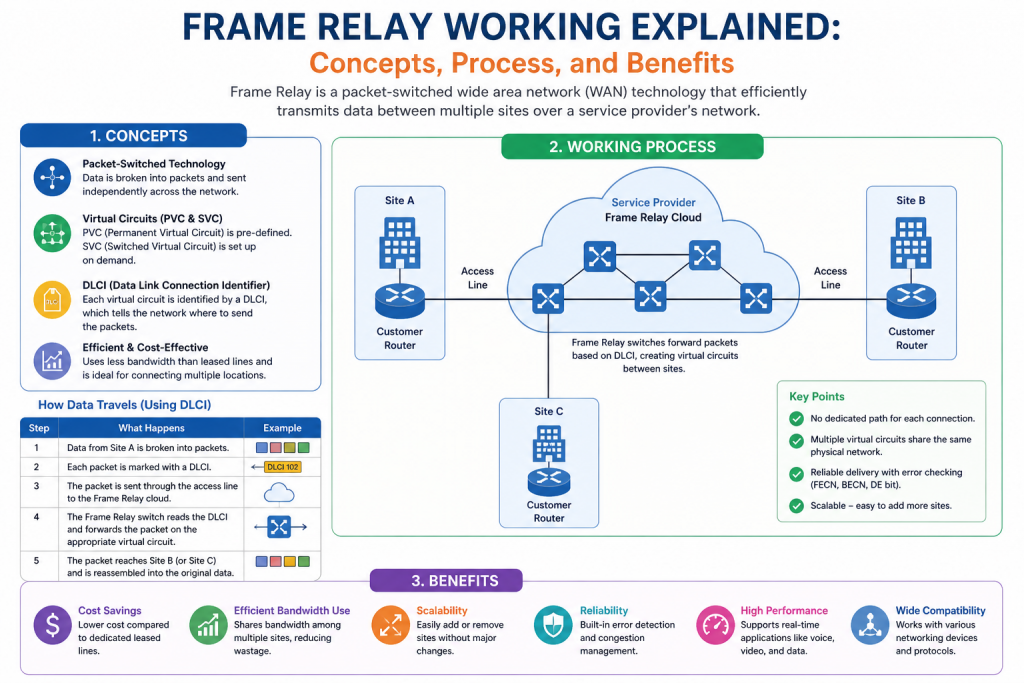
The process of data transmission in Frame Relay begins when data is generated by an application. This data is passed down through the network layers until it reaches the data link layer, where it is encapsulated into a frame.
Each frame contains a payload, which is the actual data being transmitted, and a header, which includes control information needed for delivery. One of the most important pieces of information in the header is the Data Link Connection Identifier.
Once the frame is created, it is sent into the Frame Relay network. Unlike traditional circuit-switched networks, where a fixed path is reserved for communication, Frame Relay uses shared infrastructure. This means that multiple frames from different users can travel across the same physical network simultaneously.
As the frame moves through the network, it is forwarded by Frame Relay switches. These switches use the information in the frame header to determine the correct destination. Instead of examining complex routing information, they rely on the Data Link Connection Identifier to quickly forward the frame.
One of the key advantages of this approach is efficiency. Since Frame Relay does not perform heavy error correction or path establishment for each transmission, it can forward data more quickly than older technologies.
Another important characteristic is that frames may take different paths to reach the destination. This is because Frame Relay is a packet-switched technology. Each frame is treated independently, allowing the network to dynamically distribute traffic based on availability and congestion.
Once the frame reaches its destination, it is reassembled into the original data and passed up through the OSI layers until it reaches the receiving application.
Virtual Circuits and Logical Connectivity
A fundamental concept in Frame Relay is the use of virtual circuits. These circuits provide logical connections between two endpoints without requiring a dedicated physical link.
Virtual circuits allow devices to communicate as if they are directly connected, even though the underlying infrastructure is shared among many users. This is one of the key innovations that made Frame Relay efficient and cost-effective.
There are two main types of virtual circuits used in Frame Relay.
The first type is the Switched Virtual Circuit. This type of connection is temporary and is established only when data needs to be transmitted. Once the communication session is complete, the circuit is terminated. Switched virtual circuits are similar to making a phone call, where a connection is created, used, and then disconnected.
The second type is the Permanent Virtual Circuit. This type of connection is always active and remains established even when no data is being transmitted. Permanent virtual circuits are more commonly used in real-world implementations because they provide consistent and reliable connectivity between sites.
Virtual circuits are identified using unique values known as Data Link Connection Identifiers. These identifiers are used by Frame Relay switches to determine how frames should be forwarded across the network.
Understanding Data Link Connection Identifiers
The Data Link Connection Identifier is a key element in Frame Relay communication. It is a numerical value assigned to each virtual circuit and is used to identify and route frames within the network.
When a frame enters a Frame Relay network, it contains a DLCI in its header. This DLCI tells the network which virtual circuit the frame belongs to and where it should be sent.
One important aspect of DLCIs is that they are locally significant. This means that they only have meaning within a specific part of the network. A DLCI used on one router may represent a completely different connection on another router.
This local significance allows Frame Relay networks to scale efficiently. Instead of requiring globally unique identifiers for every connection, each device only needs to understand its own set of DLCIs.
As frames move through the network, Frame Relay switches update or interpret the DLCI values to ensure that the data reaches the correct destination. This process allows multiple virtual circuits to coexist over a shared infrastructure without confusion.
Efficiency and Design Philosophy of Frame Relay
The design of Frame Relay is based on the principle of efficiency over redundancy. Unlike older technologies that focused heavily on error detection and correction at every step, Frame Relay assumes that modern networks are relatively reliable.
By reducing error-checking overhead, Frame Relay improves transmission speed and reduces processing requirements. However, this also means that error handling is delegated to higher layers of the network stack.
Another important design feature is bandwidth sharing. Frame Relay allows multiple virtual circuits to share the same physical link. This makes it highly efficient in environments where network usage is not constant.
Instead of dedicating unused bandwidth to a single connection, Frame Relay dynamically allocates resources based on demand. This ensures that network capacity is utilized more effectively.
The simplicity of Frame Relay also made it easier to deploy and manage compared to more complex WAN technologies. Organizations could scale their networks without significant increases in infrastructure costs.
Introduction to Frame Relay Operation in Real Networks
Frame Relay is often introduced as a simple WAN technology, but its real behavior inside a network is more structured and interesting than it appears at first glance. To truly understand how it works, it is necessary to look beyond definitions and focus on what actually happens when data travels across a Frame Relay cloud.
In practical networking environments, Frame Relay functions as a middle layer between physical infrastructure and logical communication paths. It does not simply forward data like a basic switch or route packets like a router in modern IP networks. Instead, it relies on pre-established logical pathways called virtual circuits, which guide data through a shared switching environment.
These virtual circuits make Frame Relay highly efficient, but they also introduce a different way of thinking about connectivity. Unlike point-to-point leased lines, where a direct physical connection exists between two sites, Frame Relay separates the idea of physical connectivity from logical connectivity. This separation is the key to understanding how it operates.
In this part, we will explore how switching happens inside Frame Relay, how virtual circuits behave in real environments, how data flows through the network, and how devices interact with Frame Relay infrastructure.
The Frame Relay Cloud Concept
When engineers talk about Frame Relay, they often refer to something called a Frame Relay cloud. This term represents the provider’s network infrastructure that sits between customer sites.
From the customer’s perspective, the internal structure of the provider’s network is not visible. Instead, the customer only sees entry and exit points where their routers connect to the Frame Relay service. Everything in between is abstracted as a cloud.
Inside this cloud are Frame Relay switches that handle traffic forwarding. These switches are responsible for interpreting frame headers, reading DLCI values, and sending data to the correct destination.
The cloud model simplifies network design for customers. Instead of managing multiple physical connections between every site, organizations only need to connect each location to the provider once. The provider then handles all internal routing and switching between sites.
This abstraction was one of the major reasons Frame Relay became popular. It allowed complex wide area networks to be simplified into logical connections rather than physical circuits.
How Frame Relay Switching Works Internally
At the core of Frame Relay is switching. However, unlike traditional LAN switching where MAC addresses are used, Frame Relay switching relies on Data Link Connection Identifiers.
When a frame enters a Frame Relay switch, the device reads the DLCI in the frame header. This DLCI tells the switch which virtual circuit the frame belongs to.
The switch then checks its internal switching table. This table maps incoming DLCIs to outgoing interfaces and corresponding DLCIs. Based on this mapping, the switch forwards the frame toward its destination.
This process is extremely fast because it does not involve complex routing decisions. The switch is not calculating the best path for each frame. Instead, it is simply looking up a pre-defined mapping and forwarding the frame accordingly.
For example, a frame arriving with a DLCI of 102 might be mapped to an outgoing interface with DLCI 201. The switch changes the label and forwards the frame along the correct path.
This label-swapping behavior is similar in concept to modern MPLS networks, which also use labels instead of full routing lookups. In this sense, Frame Relay can be seen as a precursor to more advanced label-switching technologies.
Virtual Circuit Mapping and Logical Paths
Virtual circuits are what make Frame Relay flexible. Instead of creating a dedicated physical link between two routers, Frame Relay creates a logical path through the network.
These virtual circuits are defined in the Frame Relay switches using configuration mappings. Each mapping connects two DLCIs across different interfaces, effectively forming a communication path.
Once a virtual circuit is established, any frame sent into it will follow the same logical path. However, the physical route inside the provider network may involve multiple switches and links.
This separation between logical and physical paths allows Frame Relay to efficiently use available bandwidth. Multiple virtual circuits can share the same physical infrastructure, reducing costs and increasing utilization.
Each virtual circuit behaves like a tunnel through the network. From the perspective of the connected routers, it appears as if they have a direct connection, even though the traffic is actually being switched through multiple intermediate devices.
Permanent Virtual Circuits in Real Usage
In most real-world deployments, Frame Relay uses permanent virtual circuits rather than switched ones. Permanent virtual circuits remain active at all times, regardless of whether data is being transmitted.
This always-on behavior makes network configuration simpler. Routers do not need to establish or tear down connections dynamically. Instead, they always assume that the path is available.
PVCs are configured by service providers based on customer requirements. For example, a company with three branch offices might have PVCs connecting each branch to a central headquarters.
Each PVC is identified by a DLCI at each end. These identifiers may differ on each router because DLCIs are locally significant.
The advantage of PVCs is stability. Since the connection is always active, there is no delay associated with establishing a session. This makes them ideal for continuous business communication such as file transfers, database synchronization, and voice traffic.
Switched Virtual Circuits and Dynamic Connections
Although less common in real deployments, switched virtual circuits represent a more dynamic approach to Frame Relay communication.
A switched virtual circuit is created only when data needs to be transmitted. Once the communication session ends, the circuit is removed.
This behavior is similar to how telephone networks operate. A call is established, used for communication, and then disconnected when finished.
SVCs require more signaling and control overhead because the network must constantly create and remove connections. However, they can be useful in environments where communication is sporadic.
For example, if two sites only need to exchange data occasionally, maintaining a permanent circuit may be inefficient. In such cases, a switched virtual circuit provides a more flexible solution.
Despite this flexibility, SVCs were less commonly used in practice compared to PVCs, mainly due to their complexity and the overhead involved in maintaining dynamic connections.
Data Flow Inside a Frame Relay Network
When a device sends data through Frame Relay, the process begins at the router connected to the network. The router encapsulates the data into a Frame Relay frame and assigns the appropriate DLCI based on its configuration.
Once the frame is sent into the Frame Relay cloud, it enters the provider’s switching infrastructure. The first Frame Relay switch reads the DLCI and determines where to forward the frame.
The frame may pass through multiple Frame Relay switches depending on the network topology. At each hop, the DLCI may be updated to reflect the next segment of the virtual circuit.
Eventually, the frame reaches the destination edge router. This router removes the Frame Relay encapsulation and passes the original data up the network stack for processing.
From the perspective of the sending and receiving devices, this entire process appears seamless. They see a direct logical connection, even though multiple switching operations occur in the background.
This abstraction is one of the key strengths of Frame Relay. It hides the complexity of the underlying network while still providing efficient communication.
Bandwidth Sharing and Traffic Behavior
One of the most important characteristics of Frame Relay is its ability to share bandwidth among multiple virtual circuits.
In traditional leased line networks, each connection has dedicated bandwidth that cannot be used by others. This often leads to inefficient utilization because some links may be underused while others are congested.
Frame Relay solves this problem by allowing multiple virtual circuits to share the same physical link. This means that unused bandwidth on one circuit can be utilized by others.
This shared approach is particularly effective in environments with bursty traffic patterns. Many business applications do not send data continuously. Instead, they generate traffic in bursts.
Frame Relay takes advantage of this by dynamically allocating bandwidth as needed. When one virtual circuit is idle, its unused capacity can be used by another active circuit.
However, this also introduces potential congestion issues. If too many virtual circuits attempt to send data simultaneously, the network may become overloaded. In such cases, Frame Relay uses congestion notification mechanisms to signal devices to slow down transmission.
Frame Relay Congestion Management
Although Frame Relay is designed for efficiency, it still includes basic congestion control mechanisms. These mechanisms help prevent network overload and ensure fair usage of resources.
When congestion occurs inside the network, Frame Relay switches can mark frames with congestion indicators. These indicators inform the receiving devices that the network is experiencing heavy traffic.
There are two main types of congestion notifications. Forward explicit congestion notification indicates congestion in the direction of data flow. Backward explicit congestion notification informs the sender that congestion exists along the return path.
Devices receiving these notifications can adjust their transmission rates accordingly. This helps reduce congestion and maintain overall network stability.
Unlike modern congestion control algorithms used in IP networks, Frame Relay’s approach is relatively simple. It relies on basic signaling rather than complex adaptive algorithms.
Introduction to Practical Frame Relay Understanding
After exploring how Frame Relay is structured and how it behaves inside a network, it is important to move into the practical side of the technology. In real-world networking environments, understanding theory alone is not enough. Engineers must also understand how Frame Relay is configured, how it behaves under different conditions, how issues are identified, and why it has been replaced by modern technologies.
Frame Relay may no longer be widely used in new networks, but it still exists in legacy systems, especially in older enterprise infrastructures. Because of this, network professionals may still encounter it during maintenance, upgrades, or migration projects. Understanding how it works is important when transitioning organizations from outdated WAN technologies to modern solutions like MPLS or SD-WAN. In many cases, engineers are required to analyze existing Frame Relay configurations before replacing them to ensure smooth migration without service disruption. Knowledge of Frame Relay also helps in troubleshooting older network equipment that has not yet been fully upgraded, making it a valuable skill in real-world networking environments.
This section focuses on how Frame Relay is configured, how communication paths are established between routers, common troubleshooting methods, practical use cases, and the technologies that have replaced it in modern networking.
Basic Frame Relay Configuration Concepts
Configuring Frame Relay involves setting up logical connections between routers using DLCIs. These configurations are usually performed on serial interfaces that connect to a Frame Relay network. Each router interface must first be enabled with Frame Relay encapsulation so that it can properly interpret incoming and outgoing frames according to the protocol. After enabling encapsulation, the next step is to assign or learn DLCIs that represent virtual circuits within the service provider’s network. These DLCIs act as identifiers that allow the router to distinguish between multiple remote destinations over a single physical connection.
Once DLCIs are assigned, the administrator must define how traffic will be routed through each virtual circuit. This is done by mapping network layer addresses to specific DLCIs so that data intended for a particular destination is always sent through the correct logical path. Depending on the network design, this mapping can be configured manually or learned automatically through mechanisms like Inverse ARP.
Additionally, the interface must be properly configured to handle either point-to-point or multipoint communication scenarios. In multipoint setups, a single interface can support multiple virtual circuits, while in point-to-point setups, each connection behaves like a dedicated link. Proper configuration ensures efficient data flow, reduces misrouting issues, and allows the Frame Relay network to function reliably across all connected sites.
Each router must be configured to recognize the Frame Relay encapsulation type. Once enabled, the router can send and receive frames using the Frame Relay protocol instead of default Layer 2 encapsulation methods.
The first step in configuration is enabling Frame Relay encapsulation on the interface. This tells the router to treat incoming and outgoing data as Frame Relay frames.
After enabling encapsulation, the next step is assigning DLCIs to the interface. These DLCIs represent the virtual circuits that connect different routers across the provider network.
Each router only knows its own DLCI values. It does not need to know the full path through the network. This is part of the abstraction that makes Frame Relay simple for end devices.
Once DLCIs are assigned, mappings are created to associate remote networks with specific virtual circuits. These mappings ensure that when data is sent to a particular destination, it uses the correct DLCI.
Understanding Frame Relay Interfaces
In a Frame Relay network, routers typically connect through serial interfaces. These interfaces act as the physical entry point into the Frame Relay cloud.
However, the interface itself does not define the full communication path. Instead, it serves as a gateway into the logical virtual circuit system.
Each interface can support multiple virtual circuits simultaneously. This is known as a multipoint configuration. In such cases, a single physical interface can handle communication with multiple remote sites.
Alternatively, point-to-point configurations can be used. In this setup, each virtual circuit is treated as a separate logical interface, making configuration simpler but less flexible.
Choosing between multipoint and point-to-point depends on network design requirements. Multipoint configurations are more efficient in terms of interface usage, while point-to-point configurations are easier to manage and troubleshoot.
Frame Relay Address Mapping
One of the most important aspects of Frame Relay configuration is mapping network addresses to DLCIs. This mapping allows the router to determine which virtual circuit should be used for a given destination.
When a router sends data, it checks its mapping table to determine the correct DLCI for the destination network. It then encapsulates the data into a Frame Relay frame and sends it through the corresponding virtual circuit.
The mapping process ensures that data is always sent through the correct logical path. Without proper mapping, frames may be delivered to incorrect destinations or fail to reach their intended target.
There are two main types of mapping methods. Static mapping is manually configured by the network administrator. In this method, each destination is explicitly associated with a DLCI.
Dynamic mapping, on the other hand, uses a protocol called Inverse ARP. This protocol automatically discovers remote devices and associates them with DLCIs. This reduces manual configuration effort but requires proper network support.
Inverse ARP and Automatic Discovery
Inverse Address Resolution Protocol plays an important role in simplifying Frame Relay configuration. It allows routers to automatically learn which DLCIs are associated with which remote IP addresses. This reduces the need for manual mapping between network endpoints, making configuration faster and less error-prone.
When a router receives a Frame Relay connection, it can send Inverse ARP requests over the virtual circuit to discover the Layer 3 addresses of connected devices. Once this information is learned, it is stored in the mapping table for future use. This automatic discovery mechanism improves scalability and makes large Frame Relay networks easier to manage efficiently.
When a router receives a Frame Relay frame, it can use Inverse ARP to identify the source of the frame. It then updates its mapping table accordingly.
This automatic discovery process reduces configuration complexity, especially in large networks with many virtual circuits.
However, Inverse ARP depends on successful communication between devices. If there are configuration errors or connectivity issues, automatic mapping may fail, requiring manual intervention.
Frame Relay Troubleshooting Concepts
Troubleshooting Frame Relay involves identifying issues related to connectivity, DLCI mapping, encapsulation, and virtual circuit status.
One of the most common issues is misconfigured DLCIs. Since DLCIs are locally significant, incorrect mapping can result in communication failures between routers.
Another common problem is encapsulation mismatch. If one router is configured to use Frame Relay encapsulation while another uses a different Layer 2 protocol, communication will fail.
Interface status is also an important factor. If a Frame Relay interface is down or not properly configured, virtual circuits cannot be established.
Network engineers often use diagnostic commands to check the status of Frame Relay connections. These commands display information about active DLCIs, virtual circuit status, and traffic statistics.
By analyzing this information, engineers can determine whether the issue is related to configuration, physical connectivity, or provider network problems.
Common Frame Relay Issues in Real Networks
In real-world environments, Frame Relay networks can experience several types of issues.
One common issue is congestion. Since multiple virtual circuits share the same physical infrastructure, heavy traffic from one circuit can affect others.
Another issue is misconfigured bandwidth allocation. If traffic exceeds the agreed bandwidth limits, the provider may drop frames or mark them as low priority.
Partial connectivity is also a frequent problem. In this case, some virtual circuits may work while others fail due to incorrect DLCI mapping or routing issues.
Timing and synchronization problems can also affect Frame Relay networks, especially in older hardware configurations.
Real-World Use Cases of Frame Relay
During its peak usage period, Frame Relay was widely used in enterprise WAN networks. Companies with multiple branch offices relied on Frame Relay to connect remote locations to central data centers. It provided a cost-effective alternative to expensive leased lines, allowing organizations to scale their networks without significant infrastructure investment. Businesses could connect multiple sites through a single provider network while maintaining logical separation between different communication paths using virtual circuits. This made it easier for enterprises to centralize applications, share resources, and manage data efficiently across geographically dispersed locations while keeping operational costs relatively low and network design simpler to manage.
One of the most common use cases was corporate branch connectivity. Each branch office would connect to a central hub using a virtual circuit, allowing centralized access to applications and databases.
Another use case was data replication between data centers. Frame Relay provided a reliable way to transfer large amounts of data between geographically separated locations.
Educational environments also used Frame Relay for lab simulations. It allowed students to learn WAN concepts without requiring physical leased lines.
Service providers used Frame Relay to offer scalable WAN solutions to multiple customers over shared infrastructure.
Limitations of Frame Relay
Despite its advantages, Frame Relay has several limitations that eventually led to its decline.
One major limitation is lack of built-in error correction. Frame Relay assumes that the underlying network is reliable, which is not always the case.
Another limitation is limited bandwidth management. While it supports shared bandwidth, it does not provide advanced traffic shaping or quality of service controls.
Frame Relay also lacks strong security features. Data is not encrypted by default, which makes it less suitable for modern security requirements.
Scalability is another concern. As networks grew larger and more complex, Frame Relay became less efficient compared to newer technologies.
Modern Technologies Replacing Frame Relay
Frame Relay has largely been replaced by more advanced WAN technologies.
Multiprotocol Label Switching is one of the most common replacements. It uses label-based forwarding similar to Frame Relay but offers better performance, scalability, and traffic engineering capabilities. MPLS works by assigning short labels to packets instead of relying on long IP address lookups at every hop, which significantly speeds up data forwarding across large networks.
It also allows service providers to create highly efficient and flexible routing paths based on application needs, quality of service requirements, and network conditions. Because of these advantages, MPLS supports modern enterprise networks more effectively, especially where high reliability, low latency, and optimized bandwidth usage are required.
SD-WAN is another modern solution. It provides centralized control, dynamic path selection, and improved application performance over multiple transport types.
MPLS VPN services offered by service providers have also replaced Frame Relay in enterprise environments. These services offer better reliability, security, and flexibility.
Ethernet-based WAN solutions have also become popular due to their simplicity and high speed.
These modern technologies address many of the limitations of Frame Relay while offering improved performance and features.
Why Frame Relay Still Matters Today
Even though Frame Relay is no longer widely used, it still plays an important role in networking education.
It introduces key concepts such as virtual circuits, packet switching, and shared bandwidth usage. These concepts are still relevant in modern networking technologies.
Understanding Frame Relay helps engineers understand how WAN networks evolved over time. It also provides context for why modern technologies were developed.
In many certification programs, Frame Relay is still taught as a foundational topic because it helps learners understand more complex networking systems.
Conclusion
Frame Relay represents an important milestone in the history of networking. It introduced efficient ways to transmit data over wide area networks using virtual circuits and shared infrastructure.
Through configuration concepts, DLCI mapping, virtual circuit behavior, and switching mechanisms, Frame Relay demonstrates how logical connectivity can replace physical connections in network design.
Although it has been replaced by modern technologies such as MPLS and SD-WAN, its core principles continue to influence network architecture today.
By understanding Frame Relay, network professionals gain a deeper appreciation of how data communication has evolved and how modern networks are built on the foundation of earlier technologies.
Continue exploring the technologies and certification concepts that matter most to you.