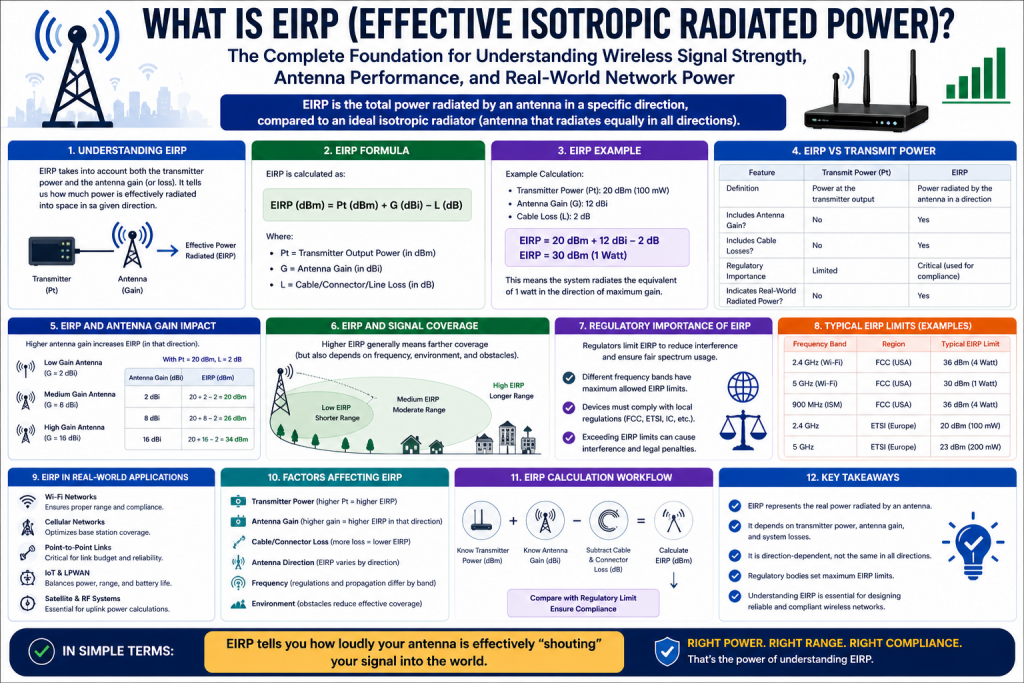
In modern wireless communication, signal performance depends on far more than simply how much power a transmitter can produce. Successful wireless networking requires understanding how radio energy is generated, shaped, directed, and received. One of the most important measurements used to evaluate this process is Effective Isotropic Radiated Power, more commonly known as EIRP.
EIRP represents the total effective power radiated by an antenna in the direction of its strongest signal, combining transmitter output, antenna gain, and system losses into one practical measurement. Rather than focusing only on raw transmitter power, EIRP gives network engineers, wireless administrators, RF designers, and IT professionals a realistic picture of how strongly a wireless signal is projected toward its intended destination.
This concept is essential because wireless systems rely on directional efficiency as much as transmitter strength. A low-powered transmitter with a highly efficient antenna may outperform a stronger transmitter using a poor antenna design. EIRP helps quantify this relationship by showing the actual usable signal power available in a target direction.
Understanding EIRP is fundamental in Wi-Fi deployments, point-to-point radio links, cellular systems, satellite communication, microwave engineering, and broadcast technologies. It directly influences coverage area, signal reliability, interference potential, and legal compliance. Whether designing a home wireless network or planning enterprise infrastructure, EIRP plays a central role in balancing performance with regulation.
At its core, EIRP bridges theory and practical networking by translating electrical power into real-world communication effectiveness.
Breaking Down the Meaning of EIRP
The term Effective Isotropic Radiated Power contains several important ideas.
“Effective” refers to the practical radiated energy after accounting for all real-world gains and losses.
“Isotropic” refers to a theoretical isotropic radiator, an ideal antenna that radiates equally in every direction like a perfect sphere.
“Radiated Power” describes the signal energy actually transmitted into space.
An isotropic antenna does not exist physically, but it serves as a standardized baseline for comparing real antennas. By comparing a real antenna’s performance against this idealized source, engineers can determine how efficiently the antenna focuses energy.
If a transmitter sends power through an antenna that concentrates energy in one direction, the effective signal in that direction becomes stronger than an isotropic radiator using the same raw power. This directional concentration is called gain.
EIRP therefore answers a critical question:
How powerful would an isotropic antenna need to be to match the signal strength produced by this real antenna system in its strongest direction?
This makes EIRP one of the most useful tools in RF system analysis.
Why EIRP Matters More Than Transmitter Power Alone
Many beginners assume wireless performance depends primarily on transmitter wattage, but this is only one piece of the puzzle.
Consider two systems:
System A:
100 mW transmitter with low-gain antenna
System B:
50 mW transmitter with high-gain directional antenna
Even though System A uses more transmitter power, System B may deliver stronger signal to a specific receiver because the antenna focuses energy more effectively.
This is why transmitter power alone cannot accurately predict wireless range or performance.
EIRP accounts for:
Transmitter power output
Cable and connector losses
Antenna gain
Directional concentration
By combining these factors, EIRP becomes a realistic measure of actual signal delivery.
This matters because wireless communication is about usable signal strength at the receiver, not just electrical output at the transmitter.
The Core Formula Behind EIRP
The standard formula for EIRP is:
EIRP = Tx Power (dBm) + Antenna Gain (dBi) − System Losses (dB)
This equation uses logarithmic units because RF systems operate across massive power ranges.
Each component serves a specific purpose:
Tx Power:
The transmitter’s raw output power before losses
Antenna Gain:
The antenna’s ability to focus signal in a preferred direction
Losses:
Signal reductions from cables, connectors, lightning arrestors, splitters, or impedance mismatches
For example:
Transmitter Power = 20 dBm
Cable Loss = 2 dB
Antenna Gain = 8 dBi
EIRP = 20 − 2 + 8 = 26 dBm
This means the final effective signal behaves like an isotropic radiator transmitting at 26 dBm.
Understanding dB, dBm, and dBi
To truly understand EIRP, it is necessary to understand the units used in RF calculations.
dB:
A relative measurement comparing one value to another
dBm:
An absolute power measurement referenced to 1 milliwatt
dBi:
Antenna gain relative to an isotropic radiator
These units simplify RF engineering because wireless power levels can vary dramatically.
For example:
0 dBm = 1 mW
10 dBm = 10 mW
20 dBm = 100 mW
30 dBm = 1000 mW (1 watt)
Every increase of 10 dBm represents a tenfold power increase.
Similarly:
3 dB roughly doubles power
-3 dB roughly halves power
This logarithmic system allows easier addition and subtraction instead of multiplying huge numbers.
How Antenna Gain Shapes Wireless Performance
Antenna gain is often misunderstood. Gain does not create extra power. Instead, it redistributes existing power more efficiently.
Imagine a bare light bulb radiating in all directions versus a flashlight focusing light into a beam.
Both may use similar energy, but the flashlight appears brighter in one direction because its reflector concentrates the light.
Antennas work similarly.
Omnidirectional antennas spread power broadly
Directional antennas focus power narrowly
Higher gain antennas reduce coverage in some directions while increasing strength in others
For example:
2 dBi antenna:
Wide coverage, lower focused strength
8 dBi antenna:
Narrower horizontal beam, stronger distance
24 dBi dish:
Extremely focused long-range communication
This is why directional antennas are ideal for point-to-point links, while omnidirectional antennas are better for local area coverage.
The Hidden Performance Killers
Even powerful systems can underperform if losses are ignored.
Common sources include:
Coaxial cable attenuation
Connector resistance
Improper cable length
Poor-quality adapters
Environmental wear
Higher frequency signals often experience more cable loss. For example, 5 GHz Wi-Fi loses more power over cable than 2.4 GHz.
A long cable run between radio and antenna can significantly reduce EIRP.
This is why professional installations often place radios close to antennas or use low-loss cable types.
Ignoring system losses can result in:
Reduced coverage
Poor throughput
Higher retransmissions
Regulatory noncompliance if calculations are inaccurate
Real-World Example of EIRP in Wi-Fi
Suppose a wireless access point transmits at 18 dBm using a 6 dBi antenna with 1 dB cable loss.
EIRP = 18 + 6 − 1 = 23 dBm
This system effectively radiates as if an isotropic source were transmitting 23 dBm.
If legal limits cap EIRP at 24 dBm, only 1 dB of margin remains.
Adding a stronger antenna without lowering transmitter power could violate regulations.
This demonstrates why EIRP is not just a performance metric but also a compliance safeguard.
Regulatory Importance of EIRP
Governments regulate wireless power to:
Prevent interference
Protect shared spectrum
Reduce signal congestion
Maintain safety standards
Wireless bands such as Wi-Fi, microwave, and outdoor bridge systems often have maximum EIRP limits.
For example:
Indoor Wi-Fi may allow moderate power
Outdoor point-to-point systems may allow higher directional EIRP
Certain frequencies require strict limitations
Exceeding EIRP limits can lead to:
Interference with neighboring networks
Reduced spectrum quality
Legal penalties
Equipment confiscation
Responsible wireless design means maximizing efficiency while staying within permitted thresholds.
Common Misconceptions About EIRP
One major misconception is that higher EIRP always means better networking.
In reality, excessive EIRP can create:
Signal distortion
Receiver overload
Interference
Poor roaming
Asymmetrical communication
For example, a powerful access point may reach a distant client, but the client’s weaker return signal may fail. Communication requires both sides to hear each other.
Another misconception is that antenna gain increases total power output. It does not. Gain only changes distribution.
Understanding these nuances prevents poor deployment decisions.
EIRP and Coverage Planning
Coverage planning involves balancing:
Range
Capacity
Interference
Antenna pattern
Client capability
In enterprise environments, excessive EIRP can cause overlapping cells and co-channel interference. Lower, optimized EIRP often improves performance more than maximum power.
In long-distance bridging, higher directional EIRP can improve stability.
The correct EIRP depends on deployment goals, environment, and regulation.
Indoor vs Outdoor EIRP Considerations
Indoor deployments prioritize:
Coverage consistency
Wall penetration
Roaming
Interference reduction
Outdoor deployments prioritize:
Distance
Line-of-sight
Weather resilience
Legal compliance
Because outdoor antennas are often high gain, EIRP can rise rapidly, making careful calculations critical.
The Strategic Role of EIRP in Modern Networking
As wireless technologies evolve into Wi-Fi 6, Wi-Fi 7, IoT ecosystems, and mesh architectures, EIRP remains central.
It impacts:
Access point design
Wireless ISP deployment
5G small cells
Satellite uplinks
Drone communications
Industrial IoT
Without understanding EIRP, network design becomes guesswork.
Moving Beyond Basic EIRP into Real-World Wireless Engineering
Once the foundational principles of Effective Isotropic Radiated Power are understood, the next step is learning how EIRP functions in real environments where physics, hardware design, environmental conditions, and regulatory frameworks all shape wireless success. In practical networking, EIRP is not merely a formula—it becomes a strategic engineering variable that determines whether a network performs efficiently, remains compliant, and scales successfully.
Wireless communication is influenced by far more than transmitter output and antenna gain on paper. Real-world deployments involve obstacles, atmospheric effects, polarization mismatches, frequency behaviors, reflection, refraction, and interference from competing systems. This means that EIRP calculations are only the beginning. True wireless mastery comes from understanding how to apply EIRP intelligently within physical environments.
For enterprise engineers, internet service providers, RF specialists, and wireless architects, EIRP serves as a planning framework that helps transform theoretical radio designs into reliable infrastructure.
The Relationship Between EIRP and Signal Propagation
Signal propagation refers to how radio waves travel through space from transmitter to receiver. Even if EIRP is high, poor propagation conditions can dramatically reduce usable connectivity.
Wireless signals can experience:
Free-space path loss
Reflection from buildings or metal surfaces
Diffraction around edges
Absorption through walls or foliage
Scattering from weather or terrain
A signal transmitted with excellent EIRP may still fail if propagation losses are severe. This is why engineers evaluate not just transmit strength but the entire link budget.
Free-space path loss increases over distance because radio energy spreads outward. The farther a receiver is from the transmitter, the weaker the signal becomes. Higher frequencies often lose strength faster than lower frequencies over similar distances.
For example:
2.4 GHz may travel farther indoors through walls
5 GHz may deliver faster speeds but shorter penetration
6 GHz may provide high throughput but more environmental sensitivity
EIRP helps maximize transmitted energy, but propagation determines how much survives the journey.
Understanding Link Budget and Why It Matters
A link budget is the total accounting of gains and losses from transmitter to receiver.
It includes:
Transmit power
Cable losses
Antenna gain
Free-space path loss
Environmental attenuation
Receiver sensitivity
While EIRP focuses on transmission strength, link budget evaluates whether communication remains viable end to end.
A strong EIRP may still fail if receiver sensitivity is insufficient.
For example:
EIRP = 30 dBm
Path Loss = 100 dB
Received Signal = -70 dBm
If receiver sensitivity is -75 dBm, the connection may work.
If receiver sensitivity is -65 dBm, the link may fail.
This demonstrates that EIRP is only one side of communication. Effective wireless design requires balancing transmitted power with receiver capability.
The Invisible Factor That Affects EIRP Success
Many wireless deployments fail not because EIRP is too low, but because the Fresnel zone is obstructed.
The Fresnel zone is the elliptical area surrounding a line-of-sight radio path where signal reflections can either strengthen or weaken communication.
If trees, buildings, or terrain intrude into this zone:
Signal cancellation may occur
Throughput may drop
Latency may rise
Packet loss may increase
Even with perfect line-of-sight visibility, Fresnel obstruction can degrade performance.
For long-distance wireless bridges, maintaining at least 60% Fresnel zone clearance is often critical.
This is why towers, rooftop mounts, and elevation calculations are essential in outdoor wireless engineering.
Antenna Polarization and EIRP Efficiency
Polarization refers to the orientation of radio wave oscillation.
Common types include:
Vertical polarization
Horizontal polarization
Circular polarization
If transmitter and receiver polarization do not align properly, signal loss can be severe.
For example:
Vertical to vertical = strong alignment
Vertical to horizontal = substantial loss
This means a system with excellent EIRP may still underperform if polarization mismatch occurs.
Proper antenna alignment improves:
Signal reception
Noise rejection
Link stability
Spectrum reuse
Polarization planning is especially important in point-to-point links, sector antennas, and microwave systems.
Directional Antennas vs Omnidirectional Antennas
Antenna type significantly affects how EIRP is distributed.
Omnidirectional antennas:
Radiate broadly in 360 degrees horizontally
Directional antennas:
Focus energy toward a specific target
Sector antennas:
Cover defined angles such as 60°, 90°, or 120°
Parabolic dish antennas:
Create extremely focused narrow beams
Each design changes practical EIRP application.
Omnidirectional use cases:
Office Wi-Fi
Public hotspots
Indoor mobility
Directional use cases:
Wireless bridges
Backhaul
Remote surveillance
Rural broadband
Directional gain can greatly increase effective range, but coverage becomes narrow. Engineers must match antenna type to deployment goals.
Beamwidth and Signal Concentration
Beamwidth describes how wide or narrow an antenna’s signal spread is.
Wide beamwidth:
Broader area, shorter distance
Narrow beamwidth:
Longer range, more precision
A narrow beam increases directional EIRP because energy is concentrated more tightly.
However, overly narrow beams require precise alignment. Small positioning errors can cause major signal loss.
This tradeoff is critical in enterprise outdoor wireless planning.
EIRP and Interference Management
Wireless communication shares spectrum. Excessive EIRP can create interference beyond intended coverage.
Common interference types include:
Co-channel interference
Adjacent-channel interference
Cross-talk
Multipath interference
Noise floor elevation
Higher power does not always improve networks. Sometimes lower, optimized EIRP improves overall capacity by reducing overlap.
For example, in dense office Wi-Fi:
Too much EIRP can cause neighboring access points to interfere
Clients may cling to distant APs instead of roaming
Network efficiency declines
Professional wireless design often prioritizes controlled power over maximum power.
Legal and Regulatory Constraints
Every country regulates wireless spectrum differently, but EIRP remains central to compliance.
Regulators establish EIRP limits to:
Protect shared frequencies
Reduce harmful interference
Prevent monopolization of airspace
Protect emergency systems
Wireless engineers must understand:
Indoor vs outdoor restrictions
Licensed vs unlicensed spectrum
Band-specific power limits
DFS requirements
Antenna gain compensation rules
In some cases, increasing antenna gain requires reducing transmitter power to maintain legal EIRP.
Failure to comply may result in:
Financial penalties
Forced shutdown
Signal complaints
Spectrum violations
Professional deployments always include regulatory calculations before implementation.
Frequency Bands and EIRP Strategy
Different wireless bands behave differently.
2.4 GHz
Longer range
Better penetration
More congestion
5 GHz
Higher speed
Shorter range
More channels
6 GHz
Very high throughput
Low interference
Shorter effective reach
Higher frequencies often require more strategic EIRP management due to path loss.
Engineers must balance:
Bandwidth
Coverage
Interference
Compliance
No single EIRP strategy works universally across all frequencies.
EIRP in Point-to-Point Wireless Systems
Long-range wireless links depend heavily on EIRP optimization.
Examples include:
Rural broadband
Campus bridging
Tower backhaul
Remote offices
These systems often use:
High-gain dishes
Precise alignment
Low-loss cabling
Clear Fresnel zones
Weatherproof hardware
A properly engineered point-to-point system can span miles, but excessive EIRP without planning can create legal or technical problems.
Weather and Environmental Impact
Rain, humidity, snow, and temperature can affect signal propagation.
Rain fade is particularly relevant in higher frequencies.
Environmental challenges include:
Tree growth
Seasonal foliage
Urban expansion
Atmospheric absorption
Salt corrosion near coastlines
An EIRP design that works today may degrade over time without environmental reassessment.
Receiver Sensitivity and Symmetry
Wireless communication is two-way.
A common mistake is boosting AP EIRP without considering client device limitations.
For example:
Enterprise AP transmits strongly
Smartphone receives signal
Smartphone lacks return power
Result:
Poor upload, dropped sessions, inconsistent connectivity
Balanced design matters more than brute-force transmission.
EIRP and Modern Wireless Technologies
Emerging technologies rely heavily on optimized EIRP:
Wi-Fi 6/6E/7
5G fixed wireless
IoT mesh systems
Satellite broadband
Smart city infrastructure
Industrial automation
As networks become denser, power efficiency and interference control become even more important.
Strategic Site Surveys and EIRP Planning
Professional deployment includes:
Spectrum analysis
Heat mapping
Signal strength surveys
Interference scanning
Capacity forecasting
EIRP should be validated through testing, not assumptions.
The Psychology of “More Power” vs “Better Design”
One of the biggest mistakes in wireless design is assuming more power equals better performance.
In reality:
Too much power may increase noise
Too much power may reduce roaming
Too much power may violate law
Too much power may create asymmetry
Better design often means:
Smarter antenna placement
Optimized channel use
Balanced EIRP
Improved receiver matching
Wireless Theory to Practical Mastery
Understanding Effective Isotropic Radiated Power at a technical level is only one part of becoming proficient in wireless networking. Real expertise comes from applying EIRP in live environments where signal quality, client behavior, hardware limitations, interference, and troubleshooting all interact continuously. In practical deployments, EIRP is not simply a specification—it becomes an operational tool used to diagnose failures, improve coverage, optimize throughput, and maintain consistent network reliability.
In homes, offices, industrial sites, public venues, rural bridges, and enterprise campuses, wireless conditions constantly change. Walls are added, devices multiply, neighboring networks appear, and environmental conditions shift. Because of this, EIRP must be monitored and adjusted alongside performance indicators like RSSI, SNR, channel utilization, retransmissions, and client roaming behavior.
Professionals who truly master wireless systems understand that EIRP is part of a larger ecosystem where transmitter power must work in harmony with receiver sensitivity, antenna placement, channel planning, and real-time troubleshooting.
Understanding RSSI and Its Relationship to EIRP
Received Signal Strength Indicator, commonly called RSSI, measures how strong a received wireless signal is at the client side. While EIRP tells you how effectively a signal is transmitted, RSSI reveals how much of that signal actually arrives at the receiving device.
RSSI is typically shown as a negative dBm value:
-30 dBm:
Extremely strong signal
-50 dBm:
Excellent signal
-67 dBm:
Good for voice and video
-70 dBm:
Usable for general networking
-80 dBm:
Weak signal
-90 dBm:
Unstable or unusable
The closer RSSI is to zero, the stronger the received signal.
A well-designed EIRP strategy should contribute to healthy RSSI levels throughout intended coverage zones. However, strong EIRP does not guarantee strong RSSI everywhere because obstacles, interference, and client limitations all affect reception.
This relationship highlights an important reality:
EIRP is about transmitted potential
RSSI is about received reality
Together, they form one of the most important diagnostic frameworks in wireless engineering.
Signal-to-Noise Ratio: Why Strength Alone Is Not Enough
A powerful signal does not automatically create a reliable network. Signal quality matters just as much as signal strength.
Signal-to-Noise Ratio (SNR) compares desired signal power against background noise.
High SNR:
Cleaner, more stable communication
Low SNR:
Poor throughput, retries, dropped sessions
For example:
RSSI = -55 dBm with noise floor -90 dBm
SNR = 35 dB (excellent)
RSSI = -55 dBm with noise floor -60 dBm
SNR = 5 dB (poor)
This means two users with identical RSSI can experience dramatically different performance.
High EIRP can improve RSSI, but if interference also rises, overall performance may still degrade.
This is why wireless optimization focuses not only on stronger signals but also on cleaner spectrum.
Common Wireless Connectivity Problems Related to EIRP
Many wireless problems are directly or indirectly tied to poor EIRP planning.
Weak Coverage Zones
Insufficient EIRP or poor antenna placement can leave dead spots where users experience low connectivity.
Overpowered Access Points
Too much EIRP may create oversized cells, causing devices to remain connected to distant APs rather than roaming to closer ones.
Asymmetrical Communication
An access point may reach clients, but client devices may lack the return power to maintain stable sessions.
Interference Expansion
Excessive EIRP can unintentionally interfere with nearby networks, increasing retransmissions.
Regulatory Violations
Improper gain upgrades without power adjustments may exceed legal EIRP thresholds.
Each of these issues demonstrates why EIRP must be approached strategically rather than maximized blindly.
Practical Troubleshooting Methodology
Effective troubleshooting begins with systematic analysis.
Verify Hardware Integrity
Check:
Cables
Connectors
Antenna mounting
Power levels
Firmware
Damaged cables or loose connectors may create hidden losses that reduce effective EIRP significantly.
Measure RSSI
Walk coverage zones and identify weak points.
Analyze Interference
Check neighboring channels, overlapping APs, Bluetooth congestion, microwave ovens, industrial noise, and physical obstructions.
Review Antenna Placement
Height, orientation, beamwidth, and physical barriers matter.
Confirm Regulatory Limits
Ensure configuration remains compliant after adjustments.
Troubleshooting is most effective when EIRP, RSSI, and environmental conditions are analyzed together.
Optimizing Antenna Placement for Better Real-World Performance
Antenna placement often influences performance more than increasing power.
Key placement considerations include:
Elevation
Clear line of sight
Distance from reflective surfaces
Reduced obstruction
Correct polarization
For example, moving an access point from behind a metal cabinet to a ceiling mount may improve performance more than increasing transmitter output by several dB.
This is because cleaner propagation often beats brute-force power.
Site Surveys: The Professional Standard
Wireless site surveys are essential for optimizing EIRP deployment.
They involve:
Coverage mapping
Heatmaps
Spectrum analysis
Capacity planning
Interference assessment
Roaming validation
Site surveys reveal where theoretical EIRP differs from practical outcomes.
For enterprise deployments, predictive surveys may be used before installation, while active surveys validate real-world performance afterward.
Without surveys, EIRP design becomes guesswork.
Channel Planning and Power Balancing
Wireless performance depends on more than power.
Proper channel planning minimizes overlap and interference.
For example:
2.4 GHz commonly uses channels 1, 6, and 11 to avoid overlap
5 GHz offers more channels but still requires planning
Excessive EIRP on overlapping channels can amplify congestion.
Professional environments often lower power intentionally to improve channel reuse and roaming.
This is especially important in:
Schools
Hospitals
Warehouses
Hotels
Stadiums
Dense AP environments benefit from controlled EIRP, not maximum EIRP.
Client Device Limitations
A network is only as strong as its weakest communication partner.
Smartphones, tablets, IoT devices, barcode scanners, and laptops all have different:
Transmit power
Antenna quality
Receiver sensitivity
Battery optimization profiles
A high-EIRP enterprise AP may still struggle if client devices are low power.
Designing around real client capability ensures balanced communication.
EIRP in Outdoor Wireless Troubleshooting
Outdoor deployments introduce additional complexity:
Wind movement affecting antenna alignment
Rain fade
Solar heat
Foliage growth
Terrain changes
Lightning protection devices
Long cable runs
In these scenarios, troubleshooting often involves physical inspections alongside RF analysis.
Directional antennas require especially precise alignment, as small angular deviations can reduce effective performance dramatically.
Using Repeaters, Mesh, and Signal Extenders
When coverage gaps exist, boosting EIRP is not always the best solution.
Alternative strategies include:
Mesh nodes
Wireless repeaters
Additional AP placement
Distributed antenna systems
Point-to-point relays
These solutions may improve user experience more effectively than raw power increases.
Enterprise Wi-Fi and Roaming Design
In business environments, wireless design prioritizes mobility.
If EIRP is too high:
Clients hold distant APs too long
Roaming delays increase
Voice calls may drop
Latency spikes
Optimized roaming often requires reducing AP power to encourage smoother transitions.
This concept surprises many beginners but is central to enterprise-grade wireless.
Security Considerations Related to EIRP
Signal range has a direct and often underestimated impact on wireless security. When EIRP is configured too aggressively, a network’s signal can extend far beyond the intended operational perimeter, creating opportunities for unauthorized users to detect, analyze, or attempt to exploit that signal from outside controlled areas. In office buildings, campuses, warehouses, and residential deployments, excessive wireless reach can unintentionally expose internal infrastructure to external threats.
Higher EIRP may unintentionally broadcast beyond intended physical boundaries, increasing security concerns such as:
Parking lot signal leakage, where attackers can access or monitor a network from nearby vehicles without entering the facility
Unauthorized interception attempts, including packet capture, reconnaissance, and traffic analysis from surrounding public spaces
Rogue association attempts, where unknown devices try to connect to exposed SSIDs
Expanded attack surface, giving adversaries more physical locations from which to launch brute-force, phishing, or wireless intrusion campaigns
Wardriving exposure, where attackers scan neighborhoods or business districts searching for visible wireless networks with weak protections
Evil twin attacks, in which attackers mimic legitimate SSIDs in areas where your signal is publicly accessible
Increased reconnaissance opportunities, allowing outsiders to identify encryption types, MAC addresses, channel structures, and vendor hardware before attempting deeper intrusion
Signal overspill can also create compliance or privacy concerns, particularly in sectors handling sensitive data. Healthcare, finance, government, and industrial environments often require stronger containment strategies because leaked wireless presence alone may reveal infrastructure patterns.
Wireless professionals balance coverage needs with containment by designing networks that deliver reliable service internally while minimizing unnecessary external reach. This often includes:
Directional antennas that focus energy only where connectivity is needed
Transmit power tuning to avoid oversaturation
Proper AP placement away from exterior walls
RF shielding materials in sensitive environments
Separate guest and internal network segmentation
Regular perimeter site surveys to detect unintended leakage zones
Advanced authentication such as WPA3-Enterprise, certificate-based access, and network access control
Power control and strategic antenna design are not just performance tools—they are security controls. By reducing unnecessary exposure, organizations shrink the geographic footprint of their wireless attack surface, making unauthorized discovery and exploitation significantly more difficult. In modern wireless security, the goal is not simply stronger coverage, but smarter containment that aligns accessibility with protection.
Monitoring and Continuous Optimization
Wireless networks are dynamic systems that continuously evolve as devices, environmental conditions, user density, software standards, and external interference patterns change over time. A wireless deployment that performs exceptionally well today may experience degraded coverage, congestion, or security vulnerabilities tomorrow due to neighboring networks, building modifications, hardware aging, or shifts in organizational demand. Because of this, wireless optimization is not a one-time deployment task—it is an ongoing operational discipline.
Best practices for maintaining high-performance wireless environments include:
Routine spectrum scans to identify new sources of interference such as neighboring Wi-Fi deployments, Bluetooth congestion, industrial equipment, or unauthorized transmitters
Firmware and software updates for access points, controllers, and client devices to patch vulnerabilities, improve compatibility, and enhance RF efficiency
RSSI trend monitoring to track gradual signal degradation, dead zones, or unusual fluctuations that may indicate hardware faults or environmental shifts
Signal-to-noise ratio analysis to ensure strong signal quality, not just signal presence
Capacity audits to evaluate whether current infrastructure can support growing device counts, IoT expansion, remote collaboration tools, and bandwidth-heavy applications
Antenna inspections for alignment drift, physical damage, weather exposure, connector wear, or mounting instability
Cable and connector validation to detect hidden attenuation, corrosion, or impedance mismatches
Compliance verification to ensure regulatory EIRP limits, DFS requirements, and channel usage remain lawful as hardware changes occur
Periodic site surveys to reassess real-world coverage after office redesigns, construction, shelving changes, or landscaping growth
Security audits to identify rogue access points, unauthorized SSIDs, weak encryption, outdated authentication protocols, or expanded perimeter leakage
Roaming performance analysis in enterprise environments to confirm seamless handoffs for voice, video, and mobile workflows
Power recalibration to prevent overpowered or underpowered cells as network density changes
Documentation updates so topology maps, channel plans, and hardware inventories accurately reflect the live environment
Wireless professionals also recognize that emerging technologies such as Wi-Fi 6E, Wi-Fi 7, private 5G, and dense IoT ecosystems can significantly alter network behavior, requiring regular architectural reassessment rather than incremental tweaks alone.
Seasonal and environmental factors can also impact network stability. Foliage growth, humidity, weather patterns, temporary structures, or new electronic equipment may all influence RF propagation. In industrial and warehouse settings, moving machinery or inventory changes can alter wireless paths unexpectedly.
An optimized network today may need recalibration tomorrow because wireless performance is shaped by constant change. The most resilient organizations treat wireless management as a continuous improvement cycle—monitoring, analyzing, adjusting, and validating performance over time. Long-term wireless excellence depends not on initial deployment alone, but on sustained operational vigilance that keeps infrastructure secure, efficient, scalable, and adaptable.
Emerging Wireless Trends and EIRP Evolution
As wireless technology advances, EIRP strategy is evolving from static power planning into a far more intelligent, adaptive, and software-driven discipline. Traditional wireless deployments often relied on fixed transmit power levels designed for broad coverage assumptions, but next-generation systems increasingly prioritize real-time optimization based on environmental awareness, user density, interference conditions, application sensitivity, and regulatory complexity. Modern wireless infrastructure is shifting away from brute-force transmission toward precision-controlled radiated power that balances performance, efficiency, security, and spectrum sustainability.
This evolution is especially important across emerging technologies such as:
Wi-Fi 7 multi-link operation, where devices can simultaneously use multiple bands or channels, requiring coordinated EIRP balancing across links to maximize throughput while minimizing congestion
Private 5G networks, which demand highly controlled signal shaping for enterprise campuses, factories, ports, and critical infrastructure with precise coverage and reduced interference
Industrial IoT ecosystems, where thousands of sensors, controllers, and machines must communicate reliably using optimized low-power transmission for scalability and battery longevity
Smart agriculture, where wide-area wireless systems support irrigation, drone telemetry, soil sensing, livestock monitoring, and autonomous equipment across large rural deployments
Autonomous systems, including vehicles, robotics, and drones, which require dynamic, low-latency wireless adaptation as movement and environmental variables constantly change
Satellite internet constellations, where advanced beamforming, phased arrays, and regulatory coordination require highly sophisticated directional EIRP strategies
Smart cities, where traffic systems, environmental sensors, emergency communications, and public access infrastructure must coexist within crowded RF ecosystems
Mission-critical healthcare and telemedicine, where wireless precision supports real-time diagnostics, remote surgery systems, and medical IoT reliability
These technologies increasingly emphasize:
Efficiency over maximum power, reducing unnecessary transmission while preserving performance
Spectrum awareness, where systems intelligently detect congestion, noise floors, and competing transmissions
Adaptive power control, allowing devices to increase or decrease EIRP dynamically based on location, signal conditions, or demand
Beamforming and directional intelligence, focusing energy only where needed
Battery-conscious operation, especially for mobile and IoT systems
Security-aware transmission boundaries, minimizing overspill and exposure
Regulatory automation, where software adjusts power automatically to maintain compliance across jurisdictions
Artificial intelligence and machine learning are becoming central to this transformation. Future wireless systems may continuously analyze RF conditions, predict congestion, optimize channel use, and adjust EIRP automatically without manual intervention. Instead of static configurations, networks will increasingly operate as self-optimizing ecosystems.
For example:
An enterprise Wi-Fi system may reduce AP power during low occupancy to conserve energy
A smart factory may raise directional EIRP only for mission-critical robotic workflows
Agricultural sensors may use adaptive low-power transmission for battery efficiency
Autonomous vehicles may alter signal focus instantly based on mobility and obstacle detection
Satellite systems may reshape beams dynamically as user demand shifts geographically
Software-defined networking, cloud-managed wireless platforms, and AI-assisted RF controllers are likely to make dynamic EIRP optimization a core pillar of future infrastructure.
This shift also reflects growing global pressure on spectrum resources. As billions of connected devices compete for finite wireless capacity, efficient radiated power management becomes essential not just for individual performance, but for broader spectrum sustainability.
Future wireless success will rely on dynamic EIRP optimization driven by software intelligence, environmental responsiveness, and predictive automation. In this new era, the most effective wireless systems will not simply transmit farther—they will transmit smarter, adapting continuously to changing conditions while maximizing speed, reliability, efficiency, and security. Mastering this transition will be critical for engineers, architects, and organizations building the next generation of connected systems.
Building a Wireless Engineering Mindset
True mastery means thinking holistically.
Ask:
Is signal reaching intended users?
Is return communication balanced?
Is interference minimized?
Is compliance maintained?
Is roaming smooth?
Is security preserved?
Is power efficient?
EIRP becomes most valuable when treated as one variable in a broader performance system.
Common Expert-Level Best Practices
Use the minimum effective power necessary
Prioritize antenna quality over brute-force wattage
Match antenna type to deployment
Validate with site surveys
Monitor RSSI and SNR continuously
Plan channels strategically
Respect legal limits
Optimize for client capabilities
Reassess environments regularly
This approach produces networks that are scalable, stable, and professional.
Conclusion
Mastering EIRP in practical networking means moving far beyond formulas into strategic wireless engineering. While Effective Isotropic Radiated Power defines how efficiently energy is transmitted, true performance depends on how that power interacts with signal propagation, client devices, environmental realities, interference patterns, and operational objectives.
When combined with RSSI analysis, SNR evaluation, site surveys, troubleshooting discipline, and optimized design principles, EIRP becomes a powerful framework for creating wireless networks that are not only functional, but exceptional.
The most successful wireless professionals understand that superior networking is rarely about maximum power. It is about intelligent power—carefully planned, precisely deployed, continuously monitored, and strategically adjusted.
In a world increasingly dependent on wireless communication, mastering EIRP is not simply a technical advantage. It is a foundational skill that separates basic connectivity from truly resilient, high-performance network engineering.
Continue exploring the technologies and certification concepts that matter most to you.